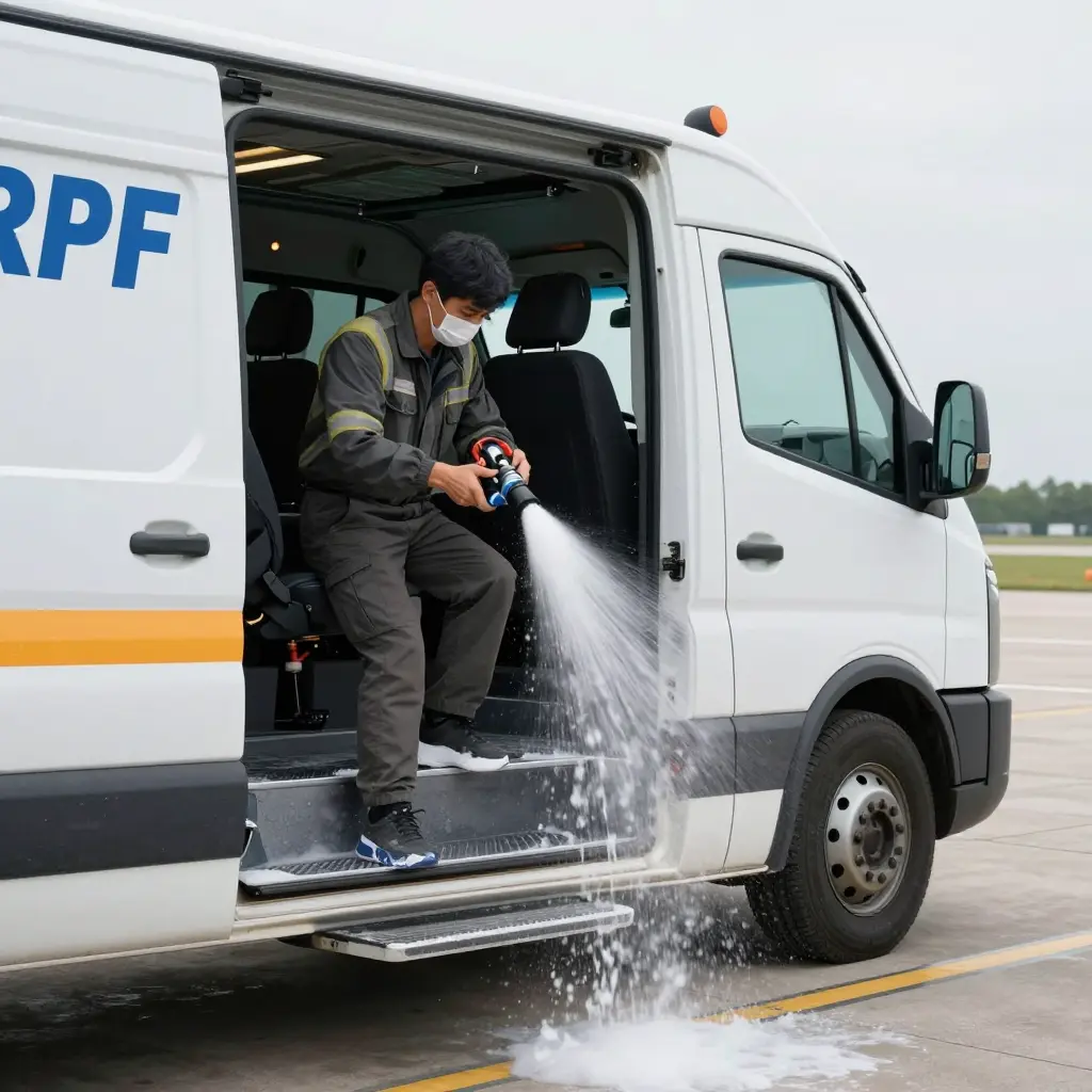
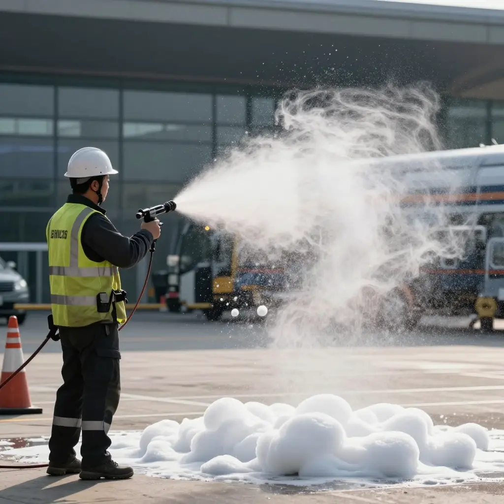
Where an airfield boundary meets a city limit, the same two kinds of fire apparatus end up working the same incident: the airport crash tender and the municipal pumper. The crash tender is a vehicle built to ARFF standards for off-runway mobility, high-rate foam delivery and fast attack on a large hydrocarbon fire. The pumper is a structural machine, organised around sustained water supply, hose-line pressure and getting lines into a building.
Mutual aid agreements put the two on the same run card because neither class covers the other’s task. Airport operators hold a regulatory obligation to keep aircraft rescue and firefighting capability available during declared emergencies, but an on-site fleet is sized for airfield coverage and can already be committed or out of service when a large aircraft incident happens. Municipal departments that border airport property bring the water, staffing and structural capability such an incident consumes, and the agreement formalises the exchange in both directions.
Two metrics decide how the pair performs together. Foam output is the volumetric rate of finished foam reaching the fire at a stated nozzle pressure and proportioning setting, in litres or gallons per minute; proportioning drift on the ramp is the most frequent reason that figure falls short of the nameplate rating. Response time to foam-on-ground is the interval from alarm to the moment finished foam touches the fuel surface, and it includes turnout, travel, positioning, line deployment and system charging.
Standards and Apparatus Classes
Apparatus class follows the standard that governs a vehicle and the variable that standard optimises, not the sheet metal. An ARFF crash tender answers to ICAO Annex 14 and Doc 9137 Part 1, which fix minimum foam application rates across the critical area – roughly 3.75 to 8.2 L/min/m², depending on airport category – along with response-time and continuous-discharge obligations. NFPA 414 governs the vehicle itself: pump-and-roll capability, a turret and bumper monitor sized for rated foam output, and the tank, foam proportioning and acceleration performance that support them. A municipal pumper answers to NFPA 1901 instead, which sets structural attack pump capacity with its 70 percent and 50 percent pressure test points, hydrant-based supply plumbing, ground monitors and handline foam systems.
The design intents diverge. ARFF apparatus maximises agent delivery density – the mass of finished foam laid on a pool fire per unit area per second – and accepts a finite onboard water load to get it. A pumper maximises sustained water from a hydrant network, trading delivery density for duration and reach into the structure.
| Parameter | Airport crash tender (ARFF) | Municipal pumper | Mutual aid operational implication |
|---|---|---|---|
| Rated foam solution output | 1,000 to 6,000 gpm (3,800 to 23,000 L/min) from all discharges combined; ICAO Category 9 requires 13,200 L/min (about 3,490 gpm) and Category 10 about 18,200 L/min (4,800 gpm) | 250 to 1,000 gpm (950 to 3,800 L/min) of solution, capped by proportioner size and concentrate carried; a 1,500 gpm pump rating does not equal 1,500 gpm of foam | One Category 9 tender out-delivers three to five mutual-aid pumpers, so verify proportioning accuracy before assigning a pumper to a foam sector |
| Fire pump capacity | Single-stage centrifugal, 1,500 to 2,500 gpm at 150 to 240 psi, driven by split shaft, PTO, or dedicated engine, rated per NFPA 414 at the full required solution output | 750 to 2,000 gpm at 150 psi, plus 70 percent of rating at 200 psi and 50 percent at 250 psi under the NFPA 1901 acceptance test | Ratings are only comparable at the same pressure; long hose lays and elevated monitors cut a pumper’s usable foam flow well below its nameplate figure |
| Onboard water tank | 1,500 to 4,000 gal (5,700 to 15,100 L); Category 9 trucks commonly carry 3,000 gal or more in baffled tanks | 500 to 1,000 gal (1,900 to 3,800 L), most often 750 gal | The tender sustains knockdown without resupply; pumpers depend on hydrants, tankers, or relay within the first two to four minutes |
| Onboard foam concentrate tank | 200 to 500 gal (760 to 1,900 L) dedicated tank, often insulated or heated, with level and temperature monitoring | 20 to 100 gal (75 to 380 L) integral tank, or no tank at all when concentrate is drawn from pails by eductor | Concentrate inventory, not pump size, sets foam duration; a pumper proportioning 6 percent at 300 gpm empties a 30 gal tank in under 100 seconds |
| Turret or monitor reach and rated flow | Roof turret 500 to 1,500 gpm (typically 1,000 gpm) with 150 to 230 ft horizontal foam throw; bumper turret 250 to 500 gpm | Deck gun 500 to 1,250 gpm with 100 to 200 ft effective reach, sensitive to nozzle pressure and crosswind | Only the ARFF turret places a blanket from a protected distance while the truck stays mobile; deck guns need a static setup and a long hose lay |
| Ground-level foam delivery (handlines, ground monitors) | One to three preconnected 1.5 to 1.75 in handlines at 60 to 250 gpm each, one or two portable monitors, total hose load usually under 300 ft | Four to six preconnects, 800 to 1,500 ft of 1.75, 2.5, and 4 in hose, hydrant supply, and heavy ground monitor capability | Municipal pumpers own the interior and ground-level foam work at a crash site; ARFF handlines are a secondary, short-duration tool |
| Pump-and-roll capability | Yes; discharge from the bumper turret while moving, typically 3 to 20 mph at 250 to 500 gpm, with a PTO-driven pump, self-protection spray, and a seated operator | Rarely; pump-and-roll exists only on quick-attack units or skid packages, and the pump operator must remain at the panel | Pump-and-roll keeps a moving truck clear of the smoke plume and heat; a pumper must stop and set the brake before foam reaches the nozzle tip |
| Governing standard | NFPA 414, plus ICAO Annex 14 airport category requirements, FAA AC 150/5220-10, and EN 1846 for European builds | NFPA 1901 for automotive fire apparatus, including its pump and foam system acceptance test chapters | Specifications are not interchangeable; an NFPA 1901 pumper carries no requirement for turret flow, acceleration, or pump-and-roll performance |
| Chassis and axle configuration | Purpose-built 4×4, 6×6, or 8×8, GVWR 40,000 to 70,000 lb, all-wheel drive with locking differentials, 0 to 50 mph in roughly 25 to 35 seconds, top speed 65 to 75 mph | Commercial or custom 4×2 or 6×4, GVWR 35,000 to 50,000 lb, single or tandem rear axle, top speed 55 to 62 mph | ARFF mobility and braking permit direct runway access and rapid repositioning; a pumper crossing the airfield needs escort and slows the response at taxiway intersections |
| Foam proportioning method | Automatic balanced-pressure or around-the-pump system with electronic flowmeters, selectable 3 and 6 percent at each discharge, and turret-specific proportioning | Around-the-pump proportioner or inline eductor, single-point injection, manual percentage selection, frequently without flow totalization | Only the tender can prove its proportioning rate in real time; pumper foam quality rests on a manual valve and operator attention |
| Secondary agent | 450 to 500 lb of dry chemical or dry powder, some builds with Halotron, delivered through the turret or a combination nozzle | None, or a single 20 lb portable extinguisher | Dry chemical knocks down a running fuel fire while the foam blanket develops; a pumper cannot replicate the effect without a skid unit |
| Crew, braking, and tyre envelope | Two to six seated positions, heavy disc brakes on all axles, high-load tyres rated for repeated 60 mph runs; brake fade and sidewall cracking are known wear points | Four to six seated positions, hydraulic disc or drum brakes rated for highway duty, standard commercial truck tyres | Sustained high-speed shuttle runs call for brake and tyre inspection at staging before the pumper takes over the water supply |
Values vary widely by manufacturer and by the airport category the vehicle is certified to, so treat these ranges as planning envelopes and confirm nameplate ratings, ICAO category, and NFPA 414 test data before writing mutual-aid assignments.
Rated vs. Delivered Foam Output
Rated foam output is a bench figure: what a pump and proportioning system deliver under controlled test conditions at a stated pressure and flow. Delivered output is what reaches the fuel surface, and the two rarely match.
Proportioning accuracy accounts for the first loss. A system holding ±10 percent at a reference flow does not hold ±10 percent in absolute terms, because the error is a ratio applied to instantaneous water flow, and at high flow rates a small percentage deviation becomes a large volumetric error in concentrate. Under-proportioning weakens the blanket and shortens drain time; over-proportioning wastes agent and can suppress expansion. Because the drift depends on flow rather than staying constant, static acceptance testing tends to miss it – the mechanism is set out in this analysis of why proportioning drift goes undetected on the ramp.
Pump-and-roll adds a second constraint. Where the drivetrain shares engine power between propulsion and the pump, available discharge falls as tractive demand rises, so a tender moving toward a fuselage may have less pump capacity than its stationary rating suggests.
Turret geometry sets a third limit. Reach measures horizontal projection, not footprint on the ground, and crosswind deflects the stream and thins the application rate where it lands, so nominal coverage area overstates wetted area. Nozzle angle and wind effects on delivered coverage are detailed in this review of turret reach and wind-induced drift.
Finally, solution output is not finished foam. Expansion multiplies volume at the nozzle, so finished foam volume has to be calculated from a measured expansion ratio and the applied flow, not from nominal solution discharge.
Where the Losses Land in Practice
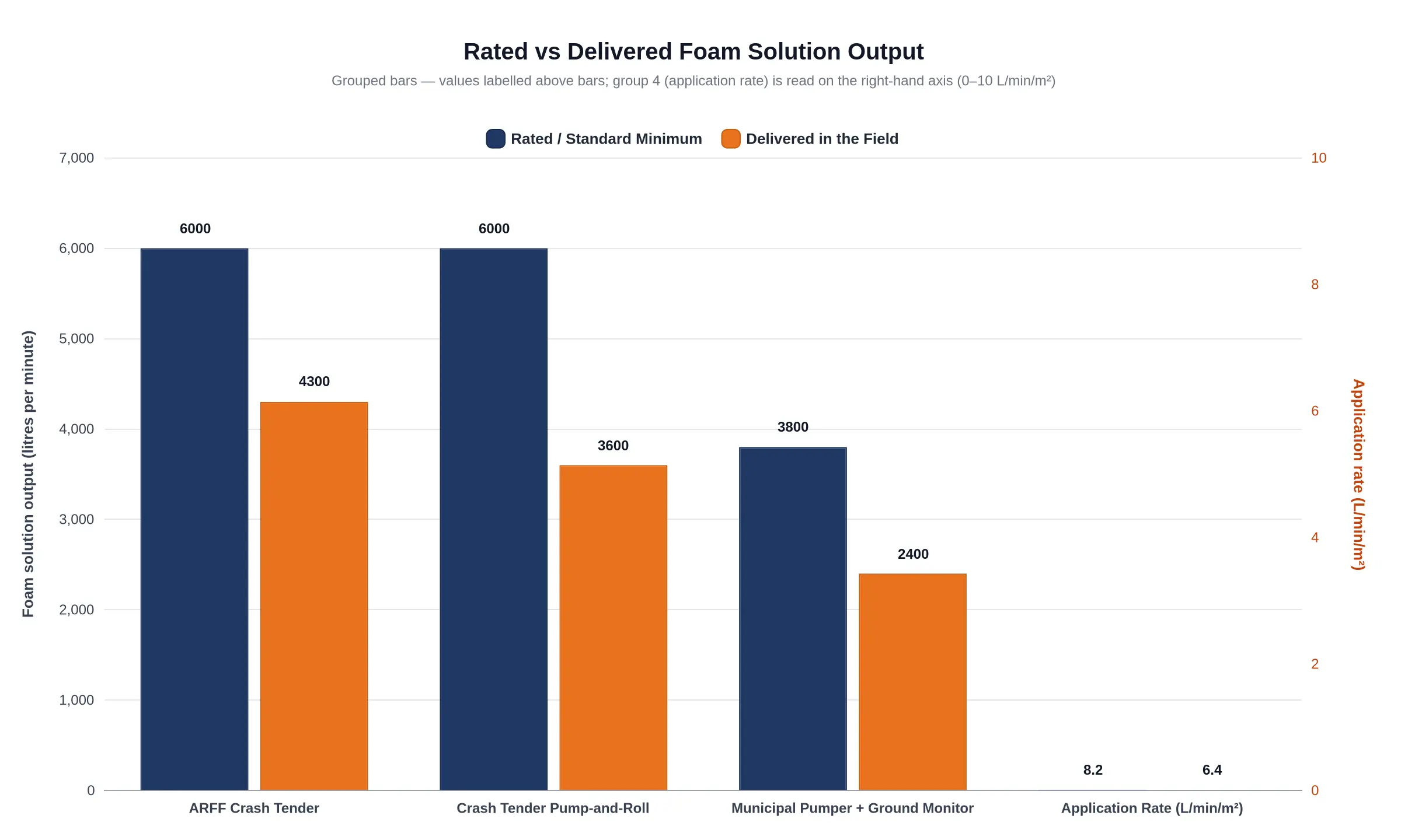
Nameplate figures are a starting point, not a prediction. The chart below groups rated and field-delivered solution output for three configurations that appear in most airport mutual aid pre-plans, plus a fourth comparison of achieved application rate against the standard minimum. The numbers are illustrative, taken from the ranges above rather than measured on one vehicle.
| Configuration | Rated / Minimum | Delivered in the Field | Shortfall |
|---|---|---|---|
| ARFF crash tender (full turret stream) | 6,000 L/min | 4,300 L/min | 28% |
| ARFF crash tender (pump-and-roll) | 6,000 L/min | 3,600 L/min | 40% |
| Municipal pumper, ground monitor + proportioner | 3,800 L/min | 2,400 L/min | 37% |
| Application rate on critical area | 8.2 L/min/m² | 6.4 L/min/m² | 22% |
A pre-plan built on nameplate litres will overstate the foam that lands on a fireground, and the error grows fastest in the configuration municipal departments are usually asked to supply: a pumper feeding a ground monitor through a long hose run. Size concentrate stock, water supply and time-to-knockdown against delivered figures. Treat pump-and-roll output as a separate line item to verify in joint drills, because the loss there comes from PTO and driveline behaviour as much as from nozzle pressure.
Delivered output rarely fails at once. It erodes through penalties that stack, and crews usually notice only when the nozzle runs watery.
- Proportioning drift and an unverified induction ratio. A proportioner can slide to 2.4 percent on a 3 percent setting without tripping an alarm, because it senses water flow, not finished foam quality. A refractometer check at the nozzle is the only honest confirmation.
- Concentrate viscosity at low temperature. Many concentrates thicken sharply below 5 °C, which raises pump demand and starves the venturi exactly when flow demand peaks.
- Pressure loss through long hose lays. Every length of 65 mm hose adds friction loss, so a long relay can leave the turret inlet well below its rated pressure with the pump at full throttle.
- Monitor and nozzle mismatch. A monitor rated for 3,800 L/min fed through a 2,400 L/min tip cannot develop its rated stream, and oversized tips drive aspiration failure instead of reach.
- Wind-driven blanket loss and runoff. Crosswinds shear finished foam off the fuel surface before it can seal, and what remains migrates toward drainage; the mechanics are covered in wind-driven runoff behaviour.
- Aeration and expansion ratio. Blocked aspirating screens and dirty foam makers drop expansion from 8:1 toward 3:1, producing wet, heavy foam with weak heat resistance and short burnback time.
- Resupply interruption. Mutual aid output depends on tanker shuttles cycling every 20 to 40 minutes. One dry tank mid-operation forces batch mixing, loses minutes and breaks the blanket over unburned fuel.
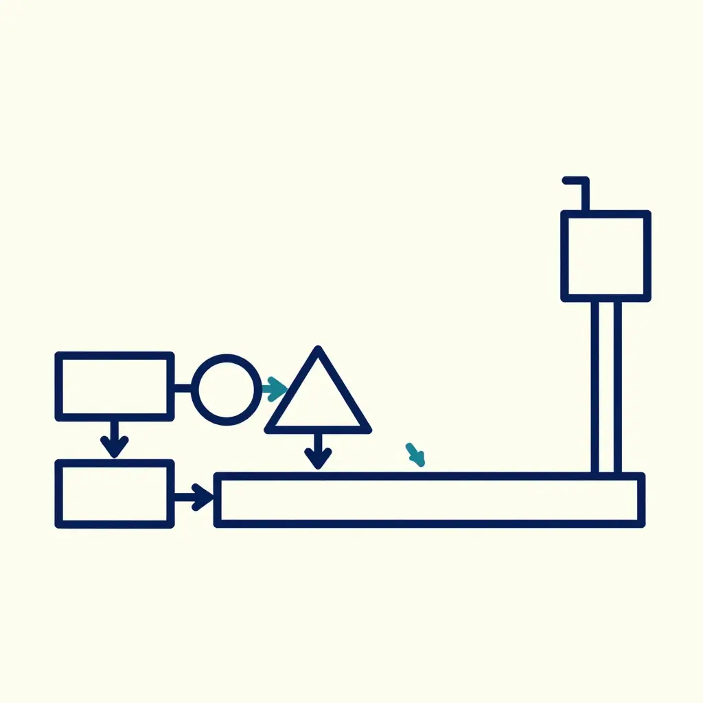
The schematic traces the chain as a single horizontal sequence: concentrate and water tanks feed the pump, the pump feeds the proportioner, the proportioner feeds the discharge line, the discharge line feeds the elevated monitor. Branch arrows mark where agent and pressure are lost. Tank capacity is inventory; the chain is delivery, and delivery is what reaches the fire. When the chain leaks energy and ratio, extra litres of concentrate buy nothing, which is why undetected proportioning drift erodes mutual aid performance long before any tank runs dry.
Response Time Analysis: Where the Clock Actually Goes
Total response time is rarely a single number. It is the sum of phases, each governed by a different constraint, and a crash tender and a pumper spend them differently.
| Phase | Airport crash tender | Municipal pumper |
|---|---|---|
| Alarm processing and turnout | Crew on station with pre-connected turret and bumper lines; turnout in seconds | Comparable dispatch, but dressing and mounting add time; station may sit farther from the incident |
| Travel from station to incident | 20-32 t mass, governed top speed, perimeter access-road limits, wet-agent load limiting acceleration | Lighter chassis, higher road speed, but traffic and grade crossings dominate |
| Arrival and positioning | Positioned for wind, egress, turret reach and nozzle angle | Positioned for hydrant or drafting site, not solely the fire |
| System setup and charging | Onboard tank plus pump-and-roll; lines charged in seconds | Hydrant establishment: forward lay, charge lines, then sustained flow |
| Foam-on-ground | Immediate from onboard water; sustained flow capped by tank volume | Sustained foam-on-ground waits on water supply, not on the foam system |
In mutual aid deployments the asymmetry decides the outcome. A pumper may reach the gate first, but its foam-on-ground clock does not start until a hydrant supply is established, often minutes after arrival. A crash tender turns its own tank into foam-on-ground within seconds and buys the supply chain time to catch up. Its penalty sits in the travel phase, where mass, access-road speed limits and brake thermal management on repeated high-speed runs eat the turnout advantage – brake fade after repeated high-speed runs is a scheduling factor, not a maintenance footnote.
Objectives are set separately. ARFF response times fall under ICAO Annex 14 and NFPA 403, which define an achievement time – typically two minutes to the runway ends and three minutes elsewhere in the operational area. Structural objectives sit under NFPA 1710 (career) and NFPA 1720 (volunteer), expressed as arrival-time percentiles rather than aircraft rescue benchmarks. Comparing apparatus without separating the phases produces misleading conclusions about which unit delivers agent first.
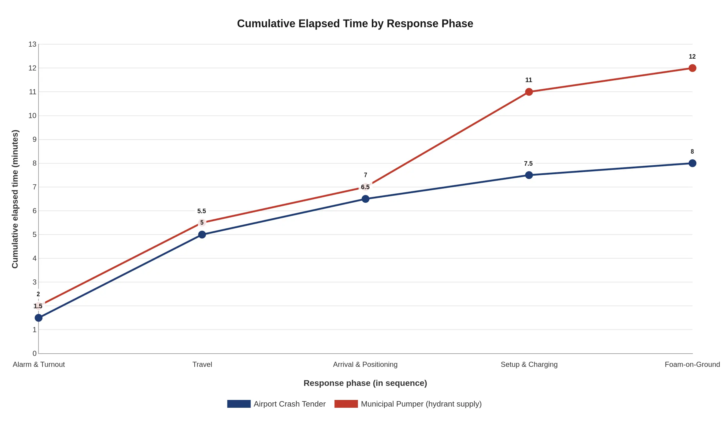
| Response phase | Crash tender (cumulative min) | Pumper from hydrant (cumulative min) | Gap (minutes) |
|---|---|---|---|
| Alarm & turnout | 1.5 | 2.0 | 0.5 |
| Travel | 5.0 | 5.5 | 0.5 |
| Arrival & positioning | 6.5 | 7.0 | 0.5 |
| Setup & charging | 7.5 | 11.0 | 3.5 |
| Foam-on-ground | 8.0 | 12.0 | 4.0 |
The two lines stay within half a minute of each other through alarm, travel and arrival and positioning, then separate at setup and charging: the gap widens from half a minute to three and a half minutes in that one phase, because the pumper cannot flow until its water supply is established. By foam-on-ground the tender is applying agent at 8.0 minutes and the pumper at 12.0, so the four-minute penalty is hydrant connection and line charging rather than travel or apparatus speed. Mutual aid timelines belong around that setup phase, not around dispatch and response distance. The phase estimates are planning figures for a run that starts away from the ARFF station; they say nothing about on-airport compliance with the two- and three-minute ICAO objective.
Mutual Aid Integration: Pairing ARFF and Municipal Pumpers
A mutual aid agreement is only as strong as the pre-incident planning behind it. Before any call, both agencies should walk each other’s ground: municipal crews through ramp access, hydrant locations and surfacing, ARFF personnel through residential street layouts, water main capacity and hydrant spacing that govern response time once units cross the perimeter fence. Cross-familiarisation on the apparatus matters as much. Pump operators need to understand the tender’s turret and proportioning controls; ARFF drivers need to understand a pumper’s intake and discharge arrangements, including the water tank integrity checks described in why airport crash tender water tank baffles crack.
Assigning Primary and Support Roles
Roles should be fixed in writing by agent type and delivery method, not by rank or arrival order.
| Function | Primary unit | Support unit |
|---|---|---|
| Aircraft fire attack | Airport crash tender (foam) | Pumper (handlines, water supply) |
| Structural fire attack | Municipal pumper | Crash tender (foam support) |
| Exposure protection | Pumper (water curtains) | Crash tender (foam blanket) |
| Sustained water supply | Pumper / hydrant | Tanker shuttle |
Unified Command and Shared Benchmarks
One incident command post with a single operations section chief keeps both classes aligned. Tactical benchmarks have to be shared, not local: state foam output as solution flow in litres per minute, application rate in litres per minute per square metre, and percentage of coverage over a defined area.
Communications follow the same logic – shared talk groups, an agreed channel plan, plain-language terminology. The division of labour stays clear: municipal crews take structural attack and exposure protection with water; the tender delivers ARFF foam application at high application rates.
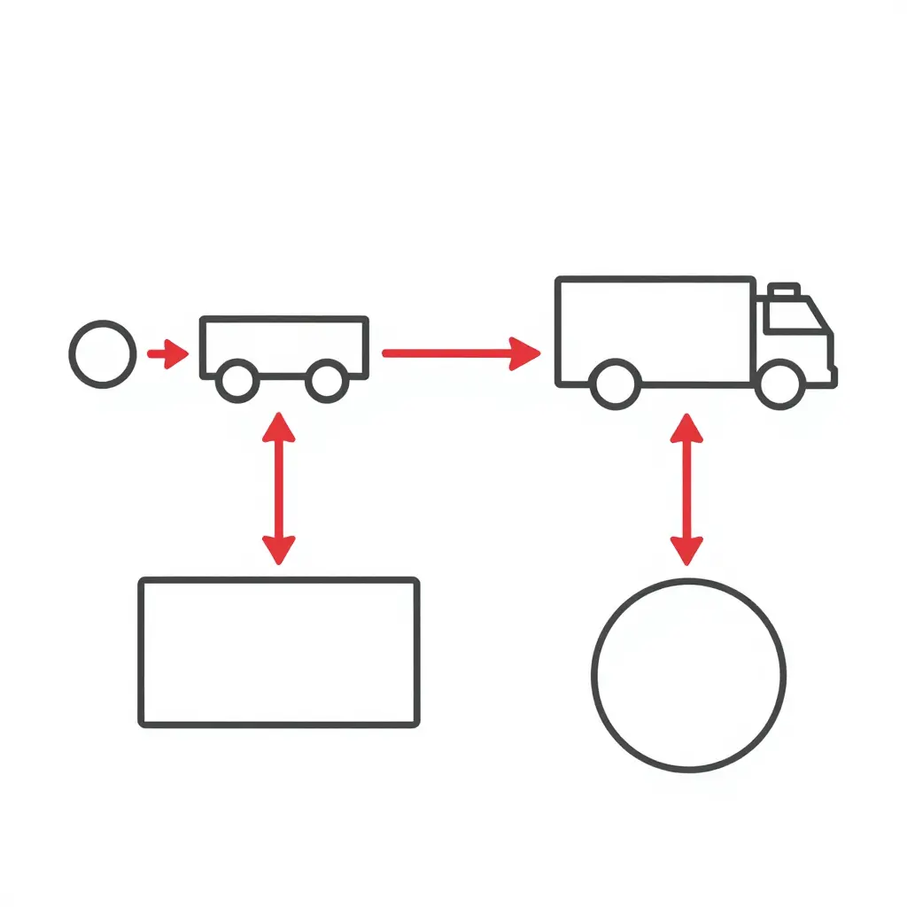
The schematic marks four interface points: hydrant intake, pumper discharge manifold, relay line to the crash tender, and the tender’s split foam and water branches feeding two target zones. Arrows show flow direction and clarify the pressure and proportioning handoffs, including where wind can distort the finished foam blanket.
Water Supply, Foam Resupply, and Logistics Sustainment
Sustaining foam output after knockdown is a supply-chain problem, not a nozzle problem. As tank volume falls, water has to arrive by relay or tanker shuttle at a rate that matches proportioning demand. In mutual aid, position the receiving pumper so intake pressure stays inside its relief valve’s working band: fluctuating supply pressure shifts the pump’s discharge reference, and a valve that cycles or dumps distorts proportioning accuracy. Relief valve dynamics under fluctuating supply are worth reviewing before committing a transfer.
Foam concentrate resupply is a container-handling job. Identify tote and pail lifting points, stage containers on hardstand, log each unit’s batch and fill date. Keep one full container in reserve per active proportioner, and schedule replenishment against measured consumption plus round-trip travel and transfer time, not against tank capacity alone. Concentrate also needs shielding from temperature extremes in storage and in transit, because repeated thermal cycling shortens agent life well before the rated date – as covered in why temperature swings shorten concentrate shelf life.
Shutoff and restart follow a fixed order: establish water flow, verify intake stability, then start concentrate injection. On shutdown, stop injection first, flush, then reduce water. Write the sequence down so crews rotating between apparatus repeat it without shortcuts.
| Response phase | Airport crash tender responsibility | Municipal pumper responsibility | Critical interface or data point to confirm pre-incident |
|---|---|---|---|
| Dispatch and turnout | Launch from the on-airport station on the ARFF alarm assignment; report full water load, concentrate quantity onboard, pump engaged, and crew staffing against the required response category. | Turn out on the mutual aid run card as water supply and foam assist only; confirm tank-to-pump valve open, concentrate tank level, and that no company is already committed to structural coverage. | Run card unit designations, shared radio talkgroup, and each rig’s verified foam solution output (L/min) at its design proportioning ratio, as reported by the driver at dispatch. |
| Travel and access | Use airport service roads and taxiway or runway access gates under ATC and airport operations control; hold current airfield driving privileges and report ETA on the operations frequency. | Travel public roads to the designated staging area outside the runway safety area; carry gate codes and accept escort and airfield driving authorization. | Gate credential and escort protocol, staging point coordinates, and the ARFF tender’s dispatch-to-arrival time from each station compared with municipal travel time, which decides who lays the first foam blanket. |
| Arrival and positioning | Position upwind and orient the turret to the fuselage or engine at the standoff distance that keeps turret reach effective; initiate pump-and-roll if the incident demands it. | Position on the unobstructed flank outside the RSA or at the designated hand-jack point; set brake and chocks, then commit to supply or foam attack per the sector assignment. | Turret reach and nozzle angle against measured wind speed (m/s), the agreed standoff line, and confirmation that the pumper will not foul the tender’s pump-and-roll path or turret arc. |
| Water supply establishment | Treat the on-board tank as the primary source until resupply; monitor tank level and pump inlet pressure, and draft from hydrant or static source through high-volume hard suction where needed. | Establish hydrant supply by forward lay or nurse to the tender; record static pressure before charging and residual pressure once the tender is flowing. | Hydrant static and residual pressure (psi or kPa) plus available flow (L/min), the tender’s fill inlet capacity and fill rate (L/min), and fill connection size and thread compatibility (Storz or other). |
| Foam application | Apply from turret or bumper at the design solution rate; verify proportioning ratio with an in-line refractometer or conductivity meter rather than trusting the panel gauge alone. | Apply through handline or ground monitor at the assigned rate; hold correct nozzle pressure and pattern, and report solution flow back to the foam sector officer. | Delivered foam solution output (L/min) each unit can actually sustain, proportioning ratio verified at the nozzle, concentrate type and brand compatibility (never mix AFFF and fluorine-free in one tank or stream), and expected expansion ratio. |
| Sustainment and resupply | Report concentrate consumption rate (L/min) and remaining minutes of foam at the current application rate to the ICP, and request replenishment early rather than at empty. | Sustain hydrant flow or tender shuttle, set up concentrate resupply from the staging cache, and manage a water shuttle if the hydrant proves inadequate. | Concentrate burn rate against on-scene stock, resupply turnaround time (min) from the nearest cache or depot, refill connection and thread match, and the storage temperature limits of the concentrate being drawn. |
| Handoff, overhaul, and release | Maintain the foam blanket and overhaul watch until formal handover; report residual agent level before any release from the scene is considered. | Assume water supply for overhaul and keep charged handlines on hot spots and wing or fuselage voids. | The formal transfer-of-command point, the trigger that allows the ARFF tender to leave without degrading blanket maintenance, and the residual agent figure reported to the ICP. |
Validate these assignments in joint exercises before they go into a signed agreement, and re-verify every proportioning figure against the apparatus and concentrate actually in use – the failure mode is set out in our analysis of why airport crash tender foam proportioning drift goes undetected on the ramp.
Procurement and Specification Implications for Mutual Aid Compatibility
For procurement specialists and fire chiefs, mutual aid is a specification problem before it is an operational one. A partner agency’s tender and your pumper may both carry impressive ratings and still deliver very different results on a shared fireground. Closing that gap belongs in the tender documents.
Start with delivered-output requirements, not rated-output claims. Require foam output to be proven at the nozzle under defined flows, with factory bench verification and on-site proportioning verification accepted by a third party. Specify monitor and turret flow ranges that bracket the partner agency’s expected application rates, so neither apparatus is pushed outside its efficient envelope. Address the fluorine-free transition explicitly by requiring foam-compatible seals and wetted parts, since legacy elastomers degrade quickly under new concentrates – see why seals and wetted parts fail first after F3 retrofits. Because mutual aid often means wet tanks and road salt, put chassis corrosion protection in the same clause set. Then standardise couplings, concentrate types and proportioning percentages across agencies.
A supplier that builds the vehicle, supplies the equipment, services it and can support the station – cimcfirerescue.com is one – can hold one specification and one support arrangement across two agencies, so the joint acceptance test has somewhere to start.
Frequently Asked Questions
Can a municipal pumper replace an airport crash tender for aircraft firefighting?
No. NFPA 414 and ICAO Annex 14 criteria assume foam output, turret reach and off-road mobility that structural pumpers do not have. A pumper can supplement ARFF under mutual aid; it cannot meet the agent application rates or the response time benchmarks.
How much delivered foam output does a crash tender lose compared with its rated output?
It depends on configuration. In the comparison above, the tender held about 72 percent of its rated solution output on a full turret stream and about 60 percent in pump-and-roll, and the pumper feeding a ground monitor held about 63 percent – losses of 28 to 40 percent. A clean turret stream with a correctly matched tip often gives up only 10 to 15 percent to proportioner error, hose friction and elevation. NFPA 412 acceptance testing measures the foam system directly; rated pump capacity on its own overstates what arrives at the turret or handline.
Which apparatus should arrive first under a mutual aid response?
The crash tender, so that foam application starts while the pumper sets up water. ICAO Annex 14 response time objectives – typically reaching the critical area within two to three minutes – apply to the ARFF vehicle, not to mutual aid units staged outside the airfield perimeter. The pumper’s arrival order is therefore a supply decision rather than a compliance one.
How should mutual aid partners verify foam proportioning accuracy together?
Run joint flow tests with an inline refractometer or conductivity meter at the nozzle, comparing measured concentration against the manufacturer’s induction ratio. Record pump discharge, foam output and proportioner setting for each apparatus. Retest annually, and after any service, because proportioning drift goes undetected on the ramp until someone measures it.
What single specification clause most improves mutual aid foam output compatibility?
A clause requiring every mutual aid apparatus to carry foam concentrate listed to the same standard and proportioned at the same percentage. Matching induction ranges and discharge fittings then keep combined output usable, whichever department’s pumper arrives.
What the Comparison Is Good For
None of this argues for choosing one class over the other. It argues for measuring two things. Foam output is a delivered-output problem: what matters is the volume reaching the spill fire at the nozzle, after proportioning accuracy, pump condition and plumbing losses, and that figure has to be measured rather than assumed. Response time is a phase problem: dispatch, turnout, gate access, positioning and application each consume time, and the two classes consume it differently. Mutual aid succeeds or fails on pre-agreed interface data, because connections, concentrations and talk groups decide whether two apparatus work as one resource. Joint verification of both metrics is what makes the rest of the plan usable.