Introduction
Airport crash tender brake fade is a thermal problem before it is a wear problem. Repeated high-speed emergency runs overheat the brake discs long before the pads wear down, and that fact shapes how these vehicles are specified, driven, inspected, and maintained.
A crash tender does not brake like a road vehicle. It accelerates 30 tonnes or more to highway speed, holds that speed to the runway threshold, then stops hard on command. Every stop converts kinetic energy into heat faster than the brake assemblies can shed it. Across repeated runs, disc temperatures climb into the range where the friction coefficient collapses and the brakes fade – while the friction material is still well inside its wear envelope.
Pad inspection on its own will not catch a thermally degraded brake system. Pads can still look serviceable while the discs and calipers operate beyond their designed heat capacity. Treating fade as a heat-management problem is what makes maintenance intervals realistic and stopping performance dependable when a call comes.
The Thermal Science Behind Brake Fade
Every time an ARFF vehicle sheds speed, the brake system absorbs an energy load that no other component on the truck is built to handle. Working through that load explains why discs overheat long before the pads wear out.
From Kinetic Energy to Heat
During high-speed emergency runs, an ARFF vehicle carries both substantial mass and high velocity, and its kinetic energy scales with the square of speed:
E = ½ × m × v²
A 35,000 kg crash tender braking from 80 km/h (22.2 m/s) must dissipate roughly 8.6 megajoules in a single stop. Service brakes work by converting motion into thermal energy, and nearly all of it arrives at the friction interface as heat, producing a heat flux measured in hundreds of watts per square centimetre across the pad and rotor faces.
Thermal Mass, Heat Flux, and Cooling Time
Whether a disc survives a run comes down to three interacting variables. Thermal mass (rotor mass multiplied by specific heat capacity) sets how much energy the disc can absorb before its temperature climbs. Heat flux governs how quickly that energy enters the surface layer. Cooling time – the dwell between applications – determines how much heat leaves through convection and radiation before the next stop.
Compress the cooling intervals, as happens on back-to-back alerts, and the rotor starts each stop already hot. Heat accumulates cycle after cycle until it crosses the material design threshold. That is brake disc overheating.
Thermal Fade Versus Mechanical Wear
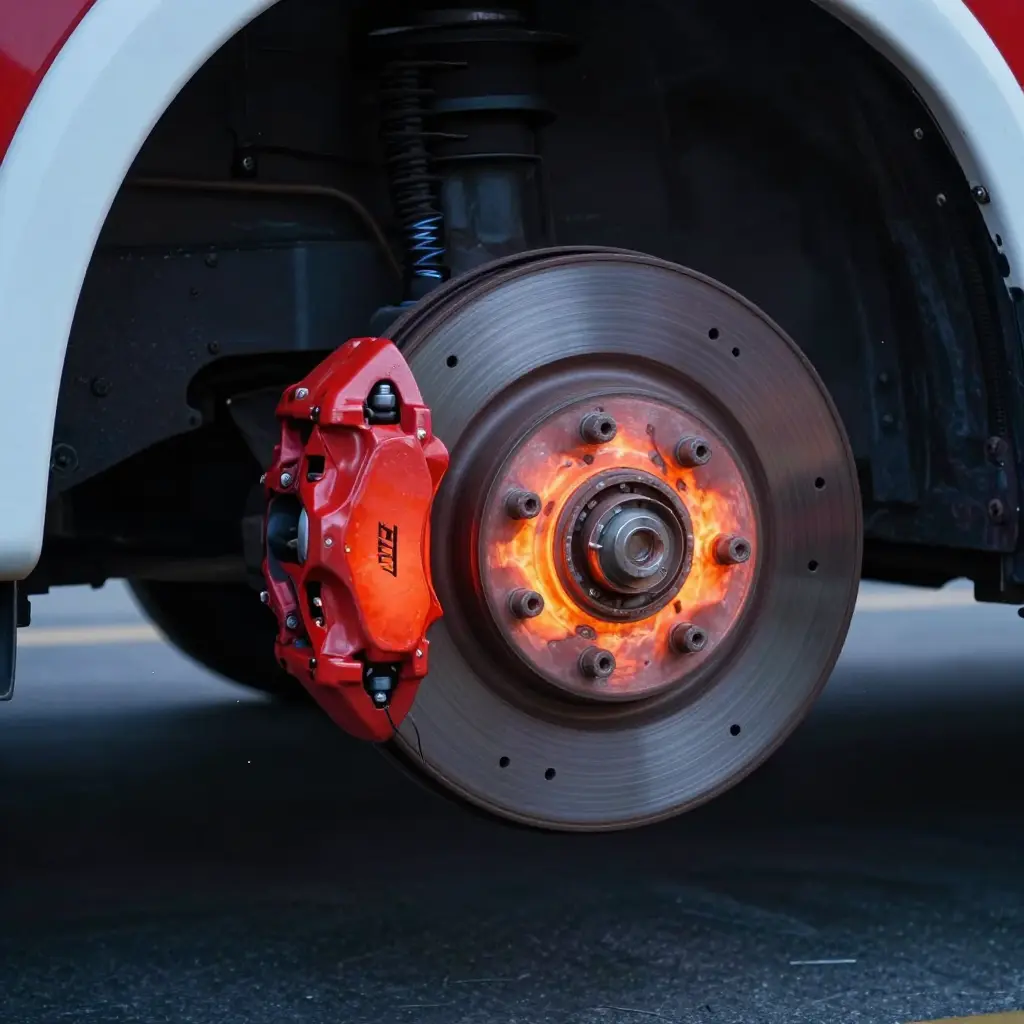
Thermal fade is a temporary loss of the friction coefficient caused by heat saturation at the pad-disc interface. As surface temperature approaches 500-650°C, the binder in the friction material begins to decompose, releasing gas and altering the friction film. The pedal can still feel firm and the pads can keep their full thickness while retardation drops sharply – a symptom some crews misread as a hydraulic fault.
Mechanical wear is the physical removal of friction material: a gradual mass loss measured in millimetres over thousands of cycles. Fade appears within minutes; wear accrues over months. That is why a crash tender can suffer severe thermal fade while its pads show almost no wear – and why rotor temperature management, not pad inspection alone, defines brake reliability in the ARFF environment.
The chart below plots brake disc temperature against the number of consecutive high-speed emergency runs, with a second line tracking pad wear remaining. The discs are already deep into fade territory while the pads are barely touched.
At run 1, the disc sits near 150 °C. Each run stacks heat faster than the disc can shed it, so the temperature climbs steeply through 340 °C (run 3), 430 °C (run 4), and 520 °C (run 5). By run 6 the disc reaches the fade threshold at roughly 550 °C, and from there the curve keeps rising to about 680 °C at run 7 and 750 °C at run 8. Pad wear remaining drifts only from 95% to 88% across the same eight runs. The most commonly inspected wear indicator says the brakes are almost untouched, while the system is thermally failing.
Why Temperature and Wear Diverge So Sharply
The two lines move on different physical timescales, which is why a pad-based inspection regime misses the problem.
- Pad wear accumulates gradually. Friction material erodes in proportion to total braking energy across thousands of cycles, so one hard stop barely registers.
- Disc temperature responds within a single run. One high-speed emergency stop turns an enormous amount of kinetic energy into heat in a few seconds. Because the disc has finite mass and only passive cooling, most of that heat is still resident when the next run begins.
- Heat soak compounds. Once disc temperatures pass a few hundred degrees, convection and radiation cannot keep pace with the input, so successive runs build on each other instead of resetting.
- Fade happens in the friction couple. As the disc overheats, the coefficient of friction at the pad-disc interface drops and stopping distance grows, even though almost no material has been consumed.
Reading the Fade Threshold Correctly
The dashed threshold line at approximately 550 °C is the practical boundary where fade becomes a mission risk for a heavy crash tender. The important detail is the gap between the curves: the temperature line reaches that threshold by run 6, while the pad line still shows more than 88% of material remaining. A maintenance program that keys off pad wear alone can send out a vehicle with a thermally compromised braking system and a spotless pad readout.
What This Means for Maintenance
For fleets running repeated drill circuits or extended emergency responses, the practical takeaways are straightforward:
| Indicator | Detects problem early? | What it actually reflects |
|---|---|---|
| Pad wear remaining | No | Long-term cumulative erosion (thousands of cycles) |
| Disc temperature / heat soak | Yes | Short-term thermal loading (minutes) |
| Fade / pedal response | Partially | Real-time friction loss, often too late |
The professional response is to shift emphasis from wear-based intervals toward thermal management: specify high-thermal-mass discs and appropriate pad compounds, build cool-down time into drill scheduling, and treat disc temperature as a primary health metric alongside traditional wear checks.
Why Repeated High-Speed Runs Overwhelm the Discs
The limiting factor in crash tender brake performance is rarely lining thickness. It is the thermal energy the discs must absorb inside a compressed operating window. A single high-speed emergency stop is a manageable thermal event; a rapid sequence of them is not, and the gap between the two is measured in megajoules and minutes.
The Energy Balance of One Stop
A fully loaded ARFF crash tender weighs roughly 36-40 tonnes. At 100 km/h (27.8 m/s), its kinetic energy is:
- KE = 1/2 x m x v^2 = 0.5 x 40,000 kg x (27.8 m/s)^2 ~ 15.5 MJ
That 15.5 megajoules must be converted to heat to bring the vehicle to rest. To decelerate at about 0.5 g (5 m/s^2), the foundation brakes must generate a braking force of:
- F = m x a = 40,000 kg x 5 m/s^2 = 200 kN
Emergency vehicles routinely decelerate at 0.5-0.6 g, so peak braking force approaches 200-240 kN. Nearly all of the 15.5 MJ enters the disc friction surfaces within 4-6 seconds, producing instantaneous power in the multi-megawatt range. Surface temperature rises far faster than the hub, caliper, or airflow can absorb.
Where the Heat Actually Goes
During the stop, heat conducts from the friction ring into the disc mass, then into the hub, bearings, caliper, and finally the air. The disc acts as a thermal reservoir, holding the bulk of the energy until convection can shed it. Shedding 15.5 MJ into the discs is survivable once. Repeating it is where brake disc overheating begins.
Single Stops vs. Repeated High-Speed Emergency Runs
The difference is not the energy per stop but the recovery time between them. A single event followed by several minutes of cooling returns the disc to a safe baseline.
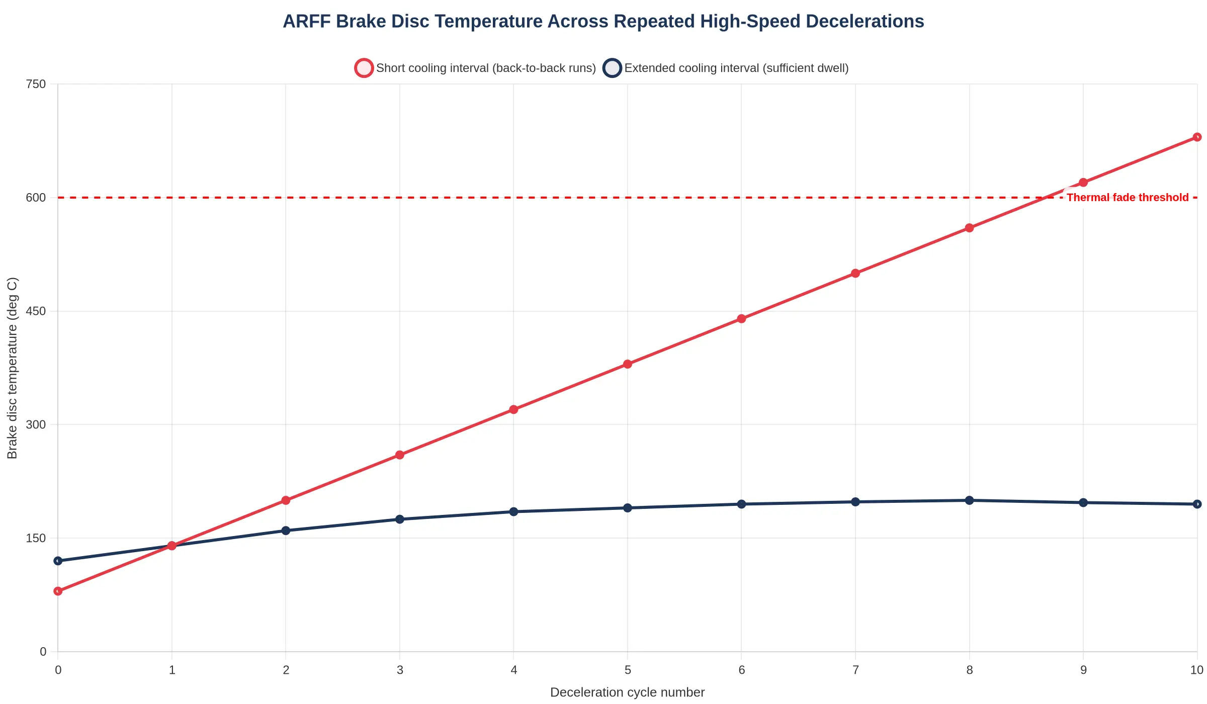
Back-to-back runs change the math. When a tender performs successive acceleration-and-stop cycles at short intervals, the discs never reach equilibrium. Convection removes only a fraction of the stored energy before the next stop adds another 15.5 MJ. Temperature stacks upward until the friction ring enters thermal fade, where the coefficient of friction collapses and braking force falls even as pedal input increases.
As the chart below illustrates, peak disc temperature climbs with each run and cools only partially between them.
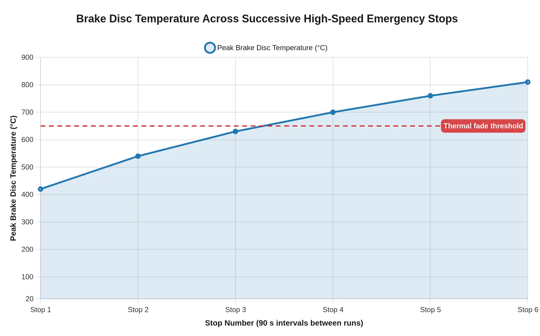
By roughly the fifth or sixth stop the discs reach the thermal fade threshold, and by the eighth they are well into the fade zone. Pad wear, by contrast, is a slow, predictable consumable. Disc overheating is a rapid, compounding event that degrades both stopping performance and rotor metallurgy long before the friction material is spent.
Disc Overheating Versus Pad Wear: A Critical Distinction
Two separate failure pathways can strip away stopping power on an airport crash tender: pad wear and brake disc overheating. Both erode braking effectiveness, so they are often confused, but they obey different physics and call for different maintenance responses.

Pad Wear: Slow, Linear, and Predictable
Pad wear is mileage-driven and gradual. Each brake application shaves a thin, consistent layer of friction material, so pad thickness declines in near-linear fashion with distance and cycle count. That predictability makes it easy to manage: measure the friction material, compare it to the minimum specification, and schedule replacement. A pad inside its thickness tolerance is treated as healthy. On a unit that idles and answers routine calls, pad wear may genuinely be the dominant concern.
Brake Disc Overheating: Fast, Temperature-Driven, and Hidden
Brake disc overheating is event-driven, not mileage-driven. A sequence of repeated high-speed runs – the exact duty cycle behind airport crash tender brake fade – pumps enormous kinetic energy into the rotor as heat. Temperature rather than distance governs performance, and it can spike within a single shift.
Once rotor and pad temperatures climb past the friction material’s design window, friction material fade begins: the resin binder softens and outgasses, forming a lubricating boundary layer that sharply lowers the coefficient of friction. If the heat persists, the surface glazes into a hard, mirror-like film that never fully recovers its bite. Thermal stress then opens micro-cracks across the rotor, and unchecked heat cracking can propagate toward structural failure.
Why Pad Thickness Checks Alone Fail
A pad within specification can still be thermally faded. Thickness measures material remaining, not material effectiveness; it says nothing about outgassing, glazing, or heat cracking. A thick pad running on an overheated disc may deliver only a fraction of its rated friction, so a routine thickness check can pass a brake that is already compromised.
Pad wear is a slow, linear, mileage story. Brake disc overheating is a fast, non-linear, temperature story.
| Parameter | Brake Disc Overheating | Pad Wear |
|---|---|---|
| Onset mechanism | Accumulated thermal energy in the rotor and friction interface exceeds the rate at which the disc can shed heat to ambient air; the pad binding layer breaks down (fade) while hardware remains physically intact. | Progressive mechanical and abrasive removal of friction material at the pad-disc interface through cumulative braking cycles; degradation is geometric, not thermal. |
| Primary driver | Repeated high-speed stops with short cooling intervals – kinetic energy of a 30+ tonne crash tender decelerating from 100+ km/h repeatedly converted to heat faster than convection can dissipate it. | Total number of service-brake applications, normal operating drag, pad compound hardness, and long-term mileage rather than any single thermal event. |
| Time scale | Minutes: can occur within a single ARFF response or across back-to-back high-speed training runs. | Months and thousands of kilometres or braking cycles; develops slowly and predictably over the pad’s service life. |
| Measurable indicator | Rotor surface temperature measured by infrared pyrometer or embedded thermocouple, typically exceeding 550 °C as it approaches the fade threshold; visible heat discolouration, bluing, or micro-cracking on the rotor face. | Remaining friction material thickness in millimetres compared to the manufacturer’s minimum specification, checked with a caliper gauge or wear-indicator sensor. |
| Effect on friction coefficient | Sharp, non-linear collapse: mu can fall from roughly 0.35-0.40 to below 0.20 as interface temperature rises, with recovery only after the disc cools. | Gradual and largely linear decline in effective mu as contact area and friction material reduce; predictable and broadly proportional to thickness loss. |
| Effect on emergency stopping performance | Sudden, severe loss of deceleration during the critical run; stopping distance stretches dramatically and total fade can leave the vehicle without usable retard under load. | Proportionally reduced but foreseeable braking authority; performance stays within design spec until the pad reaches its wear limit. |
| Inspection method | Temperature-based: infrared thermal imaging, embedded thermocouples, or brake-temperature monitoring systems, plus visual checks for rotor discolouration and cracking. | Dimensional: pad-thickness measurement with calipers or wear sensors and visual inspection of friction material condition. |
The two failure modes look superficially similar from the cab but originate from completely different physics. Disc overheating is an acute, energy-driven condition; pad wear is a chronic, cycle-driven one.
Why this justifies a temperature-based inspection approach
A pad-thickness gauge answers one question: how much material is left. It says nothing about how hot the rotor got on the last 120 km/h run – yet overheating is the failure mode that erases stopping power mid-response. Because disc overheating can develop in minutes while pad wear develops over months, a maintenance programme built solely around pad measurement can sign off a ‘healthy’ pad on a rotor already in thermal fade. Tracking rotor temperature catches the acute condition that thickness inspection is structurally blind to.
Early Warning Indicators of Thermal Brake Fade
- Repeatable heat discoloration across the rotor face – blue, purple, or straw-colored oxide bands – shows the surface has run far hotter than normal and that friction stability is degrading.
- A progressive increase in pedal travel after back-to-back high-speed emergency runs points to fluid vaporization and pad knock-back from thermal distortion, both of which lengthen the hydraulic stroke needed to produce identical retardation.
- A sharp, acrid phenolic or resin odor near the wheel end signals that the pad binder is outgassing, placing the friction couple in the fade-prone temperature band.
- A measurable drop in deceleration consistency, where repeated stops from the same entry speed yield progressively longer stopping distances, exposes coefficient-of-friction decay rather than pad thickness loss.
- Uneven hot-spot readings, typically 80 to 100 degrees C gradients across the disc face during infrared or thermal-imaging surveys, are direct evidence of localized brake disc overheating, incipient warping, and crack nucleation.
- Glazed, mirror-like pad surfaces, caused by friction material melting and smearing under excess heat, reduce both cold and hot bite and reliably precede full thermal fade.
- Pedal pulsation or steering shimmy during braking reveals disc thickness variation and thermal run-out generated by uneven cooling after repeated hard stops.
- Darkened, weeping, or recently boiled brake fluid in the reservoir, together with blistered caliper seals or melted dust boots, confirms that heat soak has moved beyond the rotor into the hydraulic and sealing components.
Read together, these signals give ARFF crews and maintainers a thermal picture of the friction couple long before pad wear becomes visible. Catching brake disc overheating early means fewer surprises on the apron, and tracking it across high-speed emergency runs turns routine post-incident checks into genuine predictive maintenance.

Figure 1 – Approximate braking heat distribution during repeated high-speed emergency runs.
Reading the thermal load
Not all brake components shoulder the heat equally. During a hard stop from 60-70 mph, the friction pair converts the vehicle’s kinetic energy into thermal energy in a matter of seconds, and that energy is partitioned in a lopsided way:
| Component | Share of thermal load |
|---|---|
| Brake disc (rotor) | ~72% |
| Brake pads | ~12% |
| Caliper & hydraulic fluid | ~8% |
| Ambient dissipation | ~8% |
The disc absorbs roughly three quarters of the thermal load. The pads are designed as sacrificial friction material; the rotor is the primary heat sink. On repeated high-speed runs with too little cooling time between them, the rotor’s temperature climbs faster than ambient air can remove the stored energy, so disc overheating becomes the limiting factor in how many back-to-back runs the truck can safely make – even while pad thickness still reads healthy.
Maintenance Implications for ARFF Fleets
Because thermal fade degrades a disc regardless of how much friction material remains, maintenance logic built on pad thickness alone leaves a blind spot. A tender can show a near-new pad profile while its rotors have already absorbed enough heat cycling to lose both friction stability and structural integrity. For fleet managers, that forces a change in how inspection and service are scheduled.
From Pad Thickness to Temperature Monitoring
The primary maintenance signal should be temperature, not material depth. Infrared pyrometry or embedded thermocouples on the front rotors let technicians log peak temperatures after each run and flag discs that repeatedly enter fade-prone ranges. This turns brake disc overheating from an invisible event into a trackable trend, and it makes pad wear a lagging indicator: by the time pads show accelerated wear, the discs have usually been overheated for many cycles already.
Cooling Intervals Between High-Speed Runs
Emergency response runs at high speed generate far more thermal load per kilometre than routine driving. Schedulers should treat airport crash tender brake fade as a function of recovery time, mandating defined cooling intervals between back-to-back high-speed evolutions so rotor temperatures fall below threshold before the next mission.
Rotor Inspection for Heat Cracks and Discoloration
Inspection points should expand to include surface discoloration (tempering colors), fine thermal crazing, and radial heat cracks. These indicate that the disc has exceeded its design envelope, even when dimensional wear is within tolerance.
Duty-Cycle Management for Training Drills
Training evolutions imitate the thermal load of real responses and must be counted against the same duty cycle. Tracking cumulative heat events across drills helps predict when a rotor is approaching end-of-life.
Why Mileage Intervals Fall Short
Standard service intervals based on distance assume a correlation between road time and brake degradation. Emergency-response vehicles break that assumption: a short high-speed run can impose more thermal stress than thousands of highway kilometres, so odometer-based scheduling systematically under-services the rotor. A program keyed to temperature and duty cycle instead of mileage keeps the braking system aligned with how the vehicle is actually used.
| Maintenance Trigger | Conventional Mileage Program | Thermal/Duty-Cycle Program |
|---|---|---|
| Primary signal | Odometer distance | Peak rotor temperature |
| Pad inspection | Scheduled interval | Condition-based, lagging |
| Rotor inspection | Wear dimension only | Cracks, crazing, discoloration |
| Run scheduling | Not considered | Mandated cooling intervals |
| Training load | Counted as distance | Counted as heat events |
Engineering Solutions for Mission-Ready Braking Systems
Brake fade on an airport crash tender is rarely an isolated component failure. It is a system-level symptom that needs a system-level response. cimcfirerescue.com is a firefighting equipment manufacturer that supplies vehicles, equipment, services, and station-building packages, and its engineering approach treats braking performance as one link in a reliability chain rather than a standalone maintenance line item.
Integrated vehicle design is the first layer of defense. Chassis architecture, axle loading, water and foam tank placement, and drivetrain retardation all shape how much thermal energy reaches the discs during a high-speed emergency run. Ventilated disc geometry, optimized cooling airflow paths, and brake hardware matched to the vehicle’s true gross weight and duty cycle lower the peak temperatures that drive fade. Heat shielding, directed airflow ducting, and onboard temperature monitoring keep friction surfaces within their design window across repeated runs, so stopping power stays predictable.
Lifecycle service support closes the loop: condition-based inspection intervals, brake fluid and caliper service schedules, and telemetry-driven diagnostics help fleets catch thermal degradation before it becomes a mission risk. The same discipline applies to the vehicle’s fluid and agent systems – foam proportioning drift can quietly degrade suppression performance even when mechanical parts look healthy, and foam concentrate storage temperature swings can shorten agent shelf life long before crews notice. Mission readiness comes from integrated design, disciplined thermal control, and continuous service support working together.
Frequently Asked Questions About Airport Crash Tender Brake Fade
How can brake discs overheat before the pads wear out?
Pad wear is driven by friction material loss over accumulated cycles, while brake disc overheating is driven by heat flux and thermal mass, not distance. During repeated high-speed emergency runs, kinetic energy converts to heat far faster than the rotor can dissipate it, so the disc reaches damaging temperatures while the friction material still retains most of its thickness. A pad can measure within specification while the disc has already begun to crack, blue, or warp.
What temperature range signals thermal fade?
On typical heavy ARFF brake systems, sustained disc temperatures above roughly 500-650°C push friction material into its fade band, where the coefficient of friction falls and brake force buys less deceleration. Temperatures beyond that band risk resin outgassing, glazing, and metallurgical change in the rotor. Real-time thermal monitoring or pyrometer checks taken immediately after runs confirm whether you are operating in this range.
How many high-speed runs trigger fade?
There is no fixed number. Fade is cumulative and depends on run length, vehicle mass, deceleration rate, and cooling airflow between stops. In practice, a crash tender making several back-to-back high-speed emergency runs with limited cooling intervals can develop fade within a single drill or incident response; successive runs stack heat faster than ducted airflow or convection removes it, so the fifth or sixth run often behaves very differently from the first.
Why don’t mileage-based service intervals work?
Brake condition on an ARFF vehicle is governed by energy absorbed, not distance travelled. A tender can cover very few kilometres yet perform dozens of full-energy stops, so an odometer-based interval badly misjudges brake disc overheating risk and can leave a compromised system in service. Intervals should be tied to thermal cycles and measured temperatures rather than to mileage alone.
What inspection steps detect disc overheating early?
Look for heat-tinting (blue or purple discoloration), fine surface crazing, radial cracking, and rotor thickness variation that shows up as pulsation under braking. Measure disc thickness and runout with a micrometer and dial gauge at every periodic inspection, and compare against the manufacturer’s minimums. Pair these measurements with post-run pyrometer readings and pad wear records to build a usable thermal history for each vehicle.
Conclusion: Maintain to Heat and Duty Cycle, Not to Pad Thickness
The evidence points to one engineering verdict: on airport crash tenders, repeated high-speed emergency runs overheat the brake discs and drive thermal fade long before pad wear becomes measurable. A wear-driven inspection schedule cannot see this failure mode, because a disc can already be metallurgically compromised while the friction material still looks serviceable.
Each emergency stop converts enormous kinetic energy into heat faster than the discs, calipers, and airflow can dissipate it, so successive runs stack temperature instead of shedding it. Once the rotor passes its critical threshold, friction coefficient drops and stopping distance grows even with fresh linings installed.
Temperature- and duty-cycle-aware programs – pyrometer or IR checks after runs, thermal logging, realistic cooling windows, and disc-condition inspection – catch degradation that thickness gauges never will.
Airport crash tender brake fade is a heat-management outcome, not a wear artifact. Treat the brake system as a thermal asset, and the fleet stays mission-ready when the next call comes.