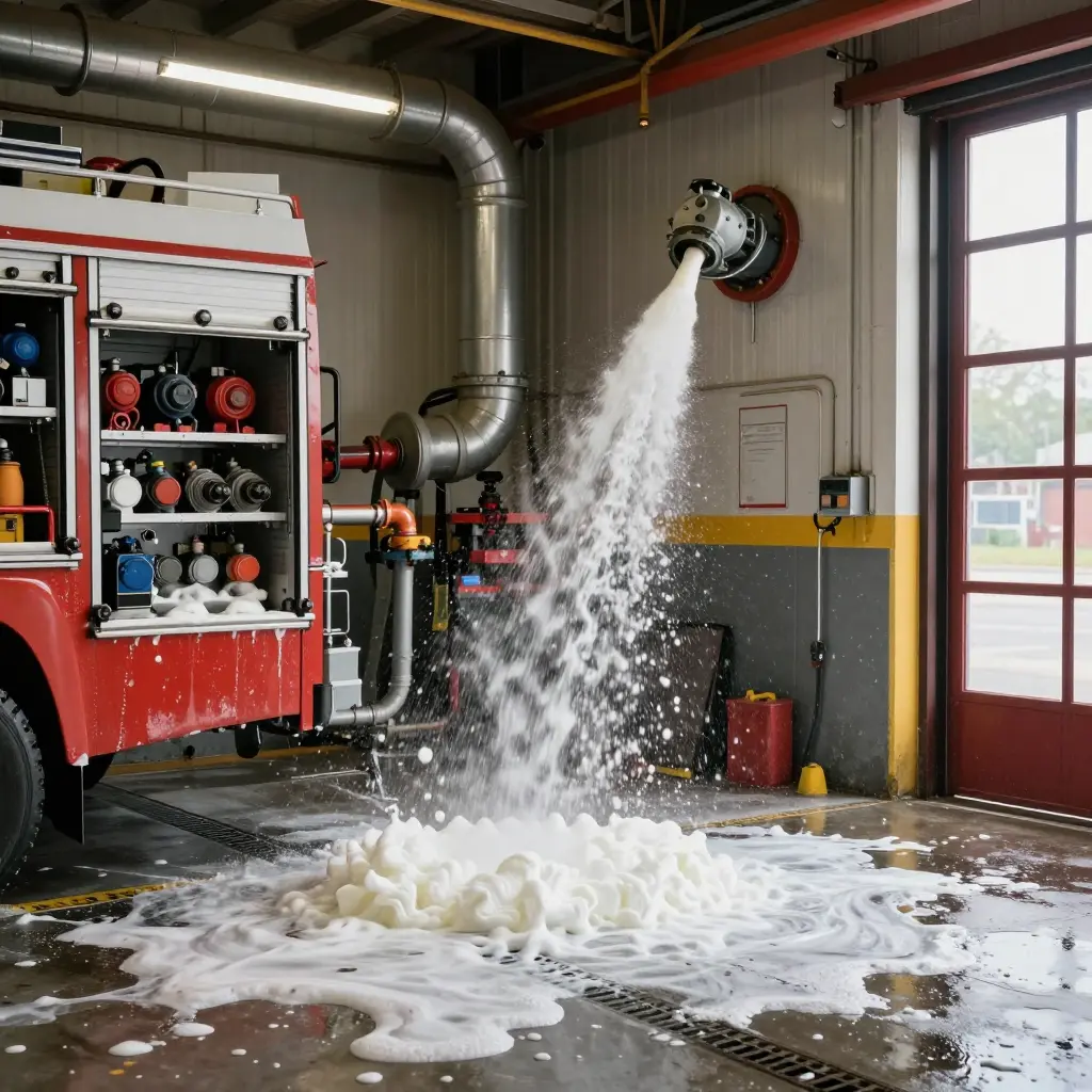
Why Apparatus Bay Drainage Must Be Planned, Not Added Later
Most of the drainage decision is made before anyone sets a trench drain in concrete. Slab thickness and control joints, the slope to the low point, door thresholds, apron grades, and where apparatus and equipment sit all determine where water can physically go. Treat drainage as a late add-on and those choices are already fixed, so the design has to work around them. Pit depth, pipe fall and separator location then get compromised in ways a planned system would not accept, which is why bay depth and layout should be settled around drainage from the first sketch.
A bay handles two different streams. Foam runoff arrives during and after a discharge, carrying diluted concentrate residue that has spread across the floor. Washdown water comes on a schedule, in larger volume over a longer period, as crews rinse apparatus, hose and slab. The two differ in peak flow, total volume and timing, and the drainage system has to serve both without letting either stream bypass treatment.
Both carry suspended solids, foam concentrate residue, and hydrocarbons picked up from engines, drivelines and tyres. Those loads set the drain sizing, the separator selection and the discharge limits the site can legally meet. No part of the layout can be settled before they are known.
Drainage Streams Your Apparatus Bay Must Be Sized For
Before you sign off on trench drain, separator or holding tank capacity, list every liquid stream the floor will actually see. A bay sized around soapy water alone will overflow the first time a crew runs a discharge test. Use the list below as the specification baseline, size for the peak combination rather than the average day, and confirm the separator handles a wind-driven foam blanket before the slab is commissioned.
- Foam runoff from discharge testing or a full foam system flush.
- Routine washdown water from floors and apparatus exteriors.
- Undercarriage and wheel-well wash water carrying grit and road film.
- Door track and threshold cleaning water with settled debris loads.
- Tank drain, overflow and sample draw-off containing residual foam runoff.
- Condensate and minor drips from air dryers and drains.
Budget the collection pit for the sum of these streams, not the average day. Foam runoff usually arrives in one concentrated surge, while washdown water trickles in across a shift. Get the sizing wrong and the shortfall shows up as ponding at the door threshold, not on the drawing.
For a closer look at how wind pushes a foam blanket toward the apron, read why foam runoff travels further than the test grid predicts.
Selection depends less on floor area than on how often you use foam and what your local discharge rules allow.
| Approach | What it captures | Layout and structural constraints | Maintenance demand | Best fit |
|---|---|---|---|---|
| Perimeter trench drain | Full-floor washdown water and spill spread | Perimeter trenching, grate frames, sloped trench invert | Grate cleaning, sediment trap desludging | High-volume washdown bays needing full coverage |
| Uniform floor slope to single outlet | All floor flow funnelled to one low point | 1-2% slab slope, outlet set below apparatus | Low routine work, outlet screen clogs | New builds with simple, cost-driven layouts |
| Slot drain across door threshold | Runoff intercepted before it leaves the doorway | Narrow threshold cut, wheel-rated frame and lid | Frequent flushing, lids lifted for cleaning | Bays where runoff must stay indoors |
| Local sump with pump-out | Pooled water and foam gathered at one low pit | Pit depth, pump access, power and conduit routing | Pump checks, sump cleaning, float and impeller wear | Retrofits and existing floors with weak slope |
| Closed-loop collection tank with haul-away | Entire foam-laden stream held for offsite disposal | Segregated piping, tank pad, tanker haul-out access | Level monitoring, periodic licensed hauling | Frequent foam use under strict discharge bans |
Foam Runoff Volume, Containment and Discharge Limits
Foam runoff does not behave like ordinary washdown water, which is why it is so easy to under-plan for. A collapsed blanket drains back into a thin, slippery film carrying a measurable load of foam concentrate residue, and that residue outlasts the visible foam by a long way. Wind makes it worse: on an open apron a drifting blanket can push liquid past the troughs you designed for, as this look at wind-driven foam spread across the apron describes. By the time runoff reaches a sample point it has mixed with hose water, rain and grit, so grab sampling is unreliable; a reading that looks compliant may just be a well-rinsed sample.
Start the volume estimate from what you actually discharge. Multiply the discharge test duration by the pump flow rate for the base figure, then add the flush water used to clear lines and rinse the rig, plus any foam that drained from the blanket itself. A short 90-second test at 4,000 L/min produces 6,000 L before a single rinse. That water is neither clean enough to discharge openly nor steady enough to treat in line, so it belongs in a collection tank, where it can be held, settled and released at a controlled rate that matches your permitted limits.
One consequence sits underneath all of it: switching to a fluorine-free concentrate changes what the separator and holding tank must tolerate, because the substitute chemistry behaves differently against seals, gaskets and coatings. The degradation patterns described in this guide to fluorine-free foam retrofit and wetted-part failure tend to surface first inside the very drainage path you are relying on.
| Planning input | What to capture |
|---|---|
| Test duration x flow | Base discharge volume per test |
| Flush and rinse water | Added volume per event |
| Blanket drainage | Residual film volume after collapse |
| Holding capacity | Settling time plus controlled release rate |
| Apparatus bay drainage | Slope, trench sizing, tank inlet screening |
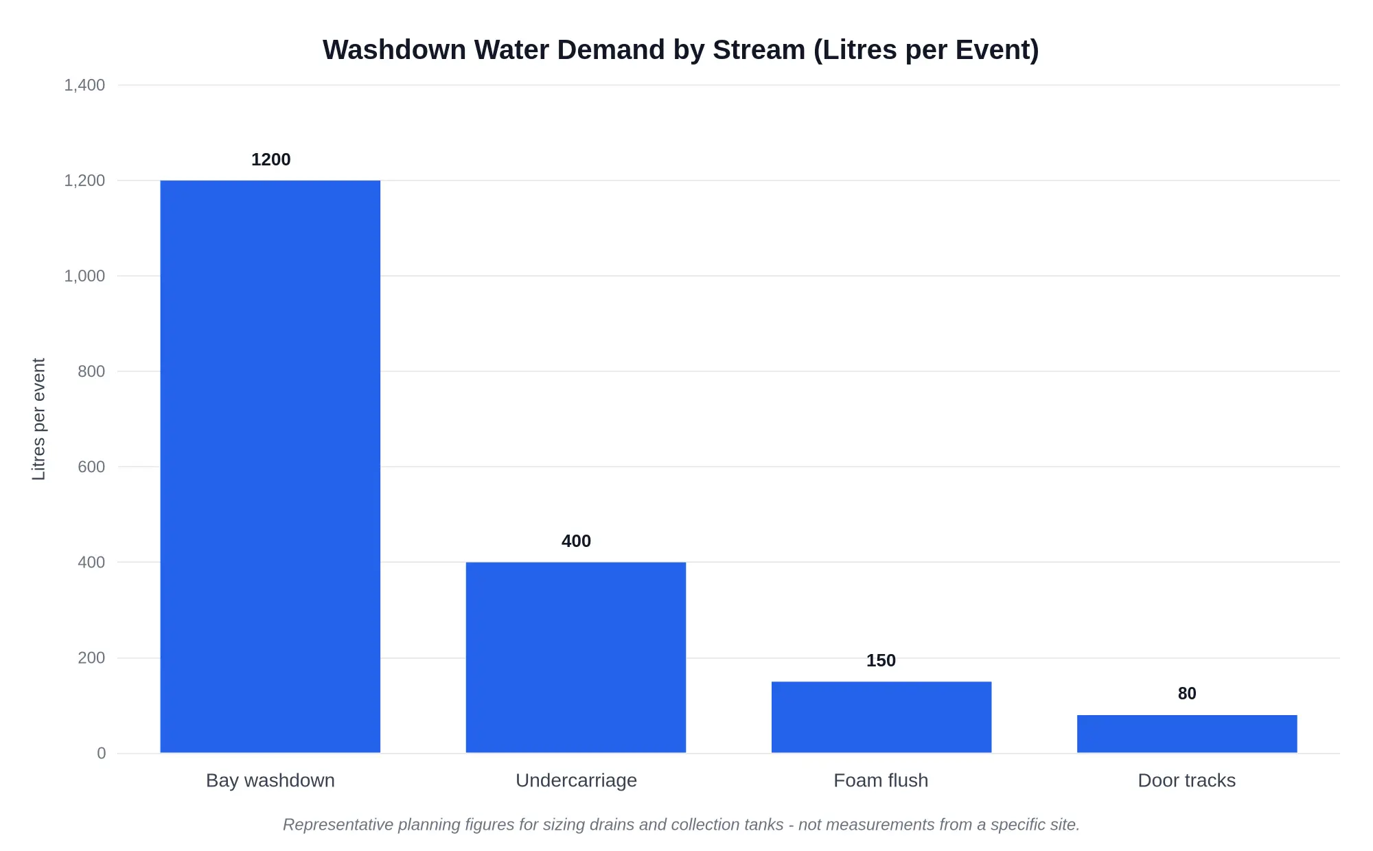
Figure: Drainage volume per event by stream (representative planning figures)
These are planning figures for sizing drains and collection tanks, not measurements from a specific site. Use them to compare relative magnitude, then scale to your own bay footprint and apparatus count.
| Stream | Representative volume per event (L) | Share of a typical cleaning cycle |
|---|---|---|
| Full bay washdown | 1200 | Dominant – sets tank and drain size |
| Undercarriage wash | 400 | Secondary |
| Post-discharge foam flush | 150 | Small, but foam-laden |
| Door track cleaning | 80 | Small, high solids |
Reading the chart: one stream decides the tank. Full bay washdown makes up the bulk of the volume in a cleaning cycle, so a collection tank sized on foam runoff alone will overflow the first time someone hoses the floor. Size for washdown, then check that the tank still gives foam-laden water enough residence time to separate before discharge. These figures cover routine cleaning only; the discharge test described above is a separate and much larger event.
Washdown Water, Separator Sizing and Maintenance Intervals
Routine washdown water is the continuous load in almost every apparatus bay. Floor rinsing, hose testing runoff, drip trays and general housekeeping produce a steady, predictable flow of lightly contaminated water, shift after shift. Foam runoff is episodic: a short, concentrated burst during a foam system test, a discharge or a cleanup, carrying far more surfactant and residue per litre than an ordinary rinse.
Size the two separately. Run the oil-water separator for the sustainable washdown flow, then give the holding tank enough surge volume to absorb the periodic foam event without short-circuiting the separator. Solids are what shorten service life: grit and sediment settle in the first chamber and take up retention volume, while foam residue and surfactants emulsify oils, slow gravity separation and blind the coalescing media, so effluent quality falls long before the unit physically fails. The same migration path turns up mechanically in this look at why wash-down water turns pump gearbox oil milky. Washdown water is a water-management problem, not just a floor-drain problem.
Sizing follows bay floor area and washdown frequency. As a planning range, budget roughly 2 to 5 litres per square metre of bay floor per rinse, multiply by the number of rinses per week to get average daily flow, then add a margin above peak washdown flow rather than sizing the separator exactly at it. Holding tank capacity usually works out at two to five rinse events plus the expected foam discharge volume, depending on how often foam systems are tested. That combination gives the oil-water separator time to work instead of being flushed straight through.
Maintenance intervals come out of the same reasoning. Check the unit visually and measure float and sludge depth monthly to quarterly, desludge when accumulated sludge and float reach roughly 25 to 50 percent of the designed capacity, and sample effluent every six to twelve months or as the discharge consent requires. Set the final intervals from your own measured accumulation trend, because solids loading from soot, grit and tyre debris, the factors behind why diesel soot settles on bay floors, is always site-specific.

Read the flow left to right: everything that hits the bay floor enters the train at the same point, and nothing leaves the site until it has passed the sampling point. That rule is what keeps a foam discharge from becoming a storm drain problem, particularly where wind-driven foam runoff can push liquid past the apron you thought you had contained.
Design Review Checklist for Apparatus Bay Drainage
Water in a fire station bay moves one way: across the slab, into the collection channel, through the separator, out to a permitted discharge point. Review the drawings in that order and nothing gets skipped. Each line below starts with an action, so it can be ticked off in one sitting with the plans open.
- Verify floor slope and fall direction before apparatus bay drainage layout is frozen.
- Check drain inlet spacing against bay length to prevent standing water.
- Size foam runoff holding capacity for the largest credible foam discharge.
- Match separator sizing to peak washdown volume rather than average flow.
- Confirm sampling point access downstream of the separator and before outfall.
- Confirm tanker and pump-out access route clear of apparatus bay drainage covers.
- Confirm clean-out and desludging access reaches every sump and chamber.
- Verify discharge permit conditions, including foam runoff limits, before sign-off.
Two items deserve extra time: holding capacity and the discharge permit. If bay length or door height is still moving, settle it first with this bay depth sizing guide, because every line above shifts once the slab footprint changes.

Above: a plan view of the bay floor only – slope arrows, perimeter trench, inlet spacing.
The thin arrows show the fall of the floor, and they all point outward to the edges rather than to a single centre point. The continuous trench around the perimeter is where almost every drop of washdown water and foam runoff ends up, not the middle of the bay. The circular inlets are spaced along that trench, and each one catches only the floor area draining toward it, so wide gaps leave runoff that is already carrying foam with a longer, slower journey.
A bay can look clean at the walls and still hold a sheen under the apparatus in the middle. Where fall is shallow, or inlets sit too far apart, foam-laden water spreads sideways as a thin film before it reaches an edge, much the way a collapsed blanket drifts as a moving sheet in wind-driven runoff. Plan the slope and the inlet spacing together and the water goes where the drawing says it should.
Owners and facility managers tend to raise the same handful of questions once a drainage plan moves from drawing to construction. These five carry the most cost and compliance risk.
Can foam runoff go straight to the storm drain?
No. In most jurisdictions, foam-laden discharge counts as industrial or trade waste, and a direct connection to a storm sewer can trigger permit violations and fines. Foam runoff carries surfactants, fluorinated or fluorine-free concentrate residue, fuels, and heavy metals washed off apparatus, none of which a municipal storm system is designed to treat. Route it to a collection or treatment path unless your local authority has explicitly approved an alternative.
Will a standard oil-water separator handle foam concentrate residue?
Only partly, and usually not well enough on its own. A conventional separator is sized around gravity separation of hydrocarbons, so dissolved and emulsified concentrate passes straight through, and the surfactant load can strip the coalescing media of its effectiveness. Units with aeration or chemical pre-treatment and a sampling point hold up better under repeated foam exposure. Confirm the separator’s rated flow against your actual discharge volume before relying on it.
How does floor slope affect drain performance?
Slope decides whether washdown water reaches the trench quickly or ponds in the low corner of the bay. Most designs run at 1 to 2 percent, roughly one-eighth to one-quarter inch per foot, with steeper local pitches at the trench lip. Too little slope leaves standing water, which lengthens dry times and speeds slab deterioration. Too much creates trip hazards and can starve shallow trench drains.
What changes when an existing bay is retrofitted with a collection tank?
The work moves from the surface into the structure. Expect slab saw-cutting for new trench runs, a tank sized in the range of a few hundred to several thousand gallons depending on apparatus count and dump-valve flow, and added pump-out access, level indication and a backwater valve to prevent surcharge. Retrofit sequencing matters, because bays usually stay in service during the work. For related layout questions, see this guide to apparatus bay depth and layout planning.
How often should separator and holding tank service be reviewed?
Treat intervals as provisional until you have real loading data from your own bay. Routine depth checks monthly to quarterly and a full service review quarterly to semi-annual are a common starting point, with pump-out driven by measured solids and free-product depth rather than the calendar alone. Review the whole apparatus bay drainage arrangement annually, including manifests, effluent sampling results and any change in foam product, since a different concentrate alters what the system has to remove.
Slope, tank volume and service interval are linked decisions, not separate line items. Aligning them on paper is far cheaper than reopening a finished slab.