Airport Crash Tender Foam Tank Vent: The Engineering Baseline
On an ARFF vehicle the foam tank vent valve is a bidirectional pressure/vacuum relief device mounted on the foam concentrate tank headspace. It is neither a filler cap nor a breather in the loose sense of the word: it is a spring- or weight-loaded assembly with two opposed functions in a single housing — vacuum relief that admits air into the tank, and pressure relief that releases air out of it. Both functions are continuously active whenever the apparatus is in service.
The valve exists because the foam concentrate tank is a sealed liquid container with a variable-volume gas space above the liquid. That gas space has to move air in and out as the liquid level changes, or the tank pressure will drift away from atmospheric.
Vacuum Relief, Pressure Relief, and the Atmospheric Headspace Requirement
During a foam attack the foam pump draws concentrate out of the tank. The liquid level falls, the headspace grows, and a negative pressure would develop above the liquid if no air could enter. The vacuum relief side of the vent valve opens at a very low differential and lets atmospheric air in, so the headspace is restored to essentially ambient pressure as the level drops. This is the function that matters most for pump performance.
The pressure relief side works in the opposite direction. When the tank is filled, liquid displaces air, and the displaced volume has to escape somewhere. The same applies to thermal expansion: concentrate in a tank sitting on a sun-exposed apparatus body expands, the level rises, and the vent releases the excess air or vapour rather than loading the shell, girth seams, and level sensor fittings with positive pressure.
The vent is sized on air flow, not liquid flow. It must pass the maximum achievable fill rate and the maximum foam pump draw rate without the tank exceeding its allowable positive or negative pressure limit, with margin left for thermal breathing and for partial blockage of the flame or vermin screen. An undersized or partially blinded vent produces pressure excursions even when the poppet is mechanically free.
Both cracking points are deliberately low, set in fractions of a bar or in inches of water column rather than in whole bar steps. The setting has to be low enough that the headspace tracks ambient pressure closely during normal draw-down, and high enough that the poppet does not chatter or pass liquid, foam residue, or moisture-laden air continuously. A soft or degraded seat and a fatigued spring both shift this setting.
Atmospheric headspace is not negotiable, because foam pump suction depends on ambient pressure pushing liquid into the impeller eye. Available suction head is atmospheric pressure, minus vapour pressure, minus suction lift and friction losses. Any vacuum standing on the headspace subtracts directly from that budget: each 0.1 bar of retained vacuum removes roughly one metre of equivalent suction head. The vent valve therefore sits in the suction path as surely as the suction hose does, and a suction path that has already lost its atmospheric reference behaves exactly like a textbook case of foam pump losing prime. The proportioning system reads a lean, unstable flow at the same time.
The vent is also a contamination path by design, being open to atmosphere. The screen, the poppet seat, and the relief body are service items, and their condition defines the pressure envelope the tank is actually operating inside.

Why a Stuck Vent Valve Pulls Vacuum and Starves the Foam Pump
The chain of events begins at the pump, not at the valve. When the foam pump withdraws concentrate from a closed tank, it removes liquid volume from a sealed container. The tank walls do not expand to make up the difference, so an equal volume of air has to enter through the foam tank vent. Air make-up is the volumetric balance that keeps the tank at atmospheric pressure while the pump runs, not an accessory function of the valve.
That balance is a flow-capacity problem, not a sizing problem. A typical ARFF foam pump delivering 3 percent proportioning at 6,000 L/min of solution demands roughly 180 L/min of concentrate, which means the vent must admit about 180 L/min of air at every instant the pump runs. A healthy vent of nominal bore can pass several times that figure at a differential of only a few kilopascals. A vent that is blocked by dried concentrate residue, iced at a condensate trap, or fitted with an over-tensioned spring cannot.
Vacuum accumulates according to the isothermal gas relationship, where headspace pressure falls in proportion to the volume removed from that headspace. With a 150 L headspace and a pump withdrawing 180 L/min, an unrestricted vent holds pressure essentially flat. If the vent passes only 170 L/min, the remaining 10 L/min is drawn out of the gas space, and headspace pressure drops at roughly 0.07 bar per minute until the vacuum relief valve opens or the pump stops. Tighten the blockage and the same arithmetic produces vacuum in seconds rather than minutes, which is why the failure is often reported as an intermittent suction problem rather than a vent problem.
Cracking pressure sets the ceiling on how much vacuum the tank will tolerate. A vacuum relief valve set to crack at 0.03 bar protects the pump because the headspace never falls far below atmospheric before air is admitted. A valve adjusted to crack at 0.15 bar, or one whose seat is bonded shut by residue, allows the headspace to fall the full 0.15 bar before any relief occurs. That differential is transmitted directly along the suction line to the foam pump suction, where it appears as an additional 1.5 m of lift that the pump was never designed to overcome, and where the resulting loss of net positive suction head explains the symptoms described in our guide to a foam pump losing prime.
The final stage is the approach to the concentrate’s vapour pressure. Foam concentrates are aqueous solutions with a vapour pressure of only a few kilopascals at operating temperatures, so once headspace vacuum approaches that figure the liquid begins to release dissolved air and then vapour at the suction eye. Cavitation follows, flow becomes unstable, and proportioning drifts rich and lean as the pump alternately recovers and breaks suction. The tank itself is rarely damaged; the pump, the seal faces and the proportioning accuracy absorb the consequences.
Stuck closed versus stuck open
A vent valve stuck closed is silent and internal. There is no external leak to find, no staining on the tank top, no odour. The evidence is behavioural: suction vacuum measured at the pump inlet, a hiss of air when the fill cap is cracked open on a tank that should be at atmospheric pressure, and symptoms that disappear when the vent line is disconnected.
A vent valve stuck open is the opposite failure and is usually obvious. Concentrate seeps or sloshes from the vent under braking, acceleration and ramp movement, leaving a sticky residue around the foam tank vent and on the deck. Concentrate odour is present in the apparatus bay. Moisture and airborne contaminants enter the headspace and condense on the tank walls, diluting the agent at the top of the charge and feeding the icing and residue problems that eventually produce a stuck-closed condition in the same valve. An open vent does not starve the pump and a closed vent does not leak, so matching the observed symptom to the correct failure mode is the first step in diagnosis.
The Air Path, Drawn Simply
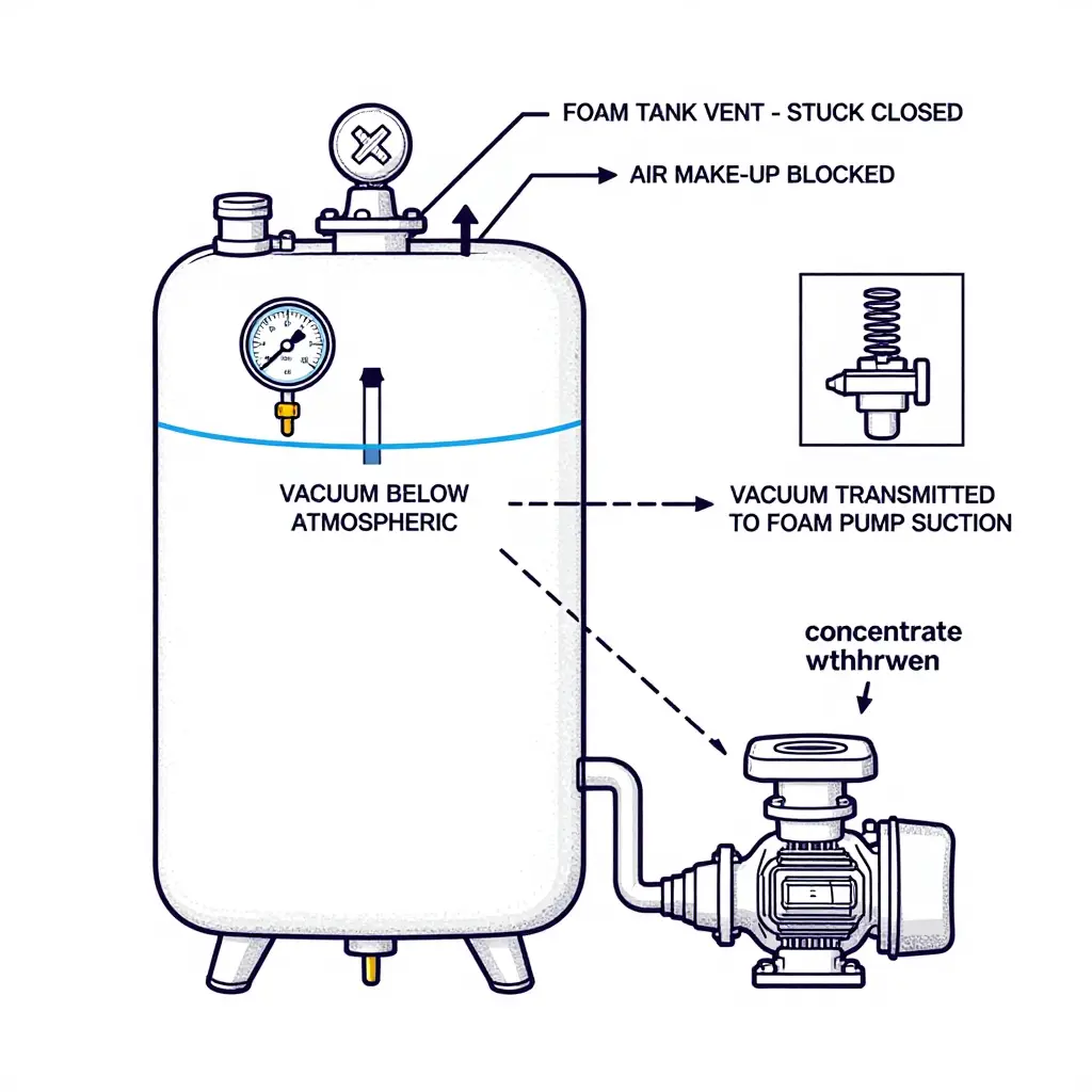
Figure 1 strips the system down to four elements: the tank shell, the vent valve on top, the suction line, and the pump. Every litre the pump pulls out of the tank has to be replaced by something, and on most ARFF tanks that something is air entering through the vent valve. Follow the solid arrows: atmosphere in, tank pressure equalised, concentrate flowing freely to the suction line.

Figure 1: Simplified 2D schematic of the tank-vent-pump air path, contrasting the intended inward air make-up flow through the vent valve with the blocked path at a seized valve seat, plus an inset showing headspace pressure acting inward on the tank shell.
On the blocked branch, with the valve seat seized, air cannot enter, so the same pump suction begins lowering the pressure inside the tank instead. That negative pressure is what eventually starves the pump, a failure mode covered in more detail in our breakdown of why an ARFF foam pump loses prime.
From Tank Vacuum to a Starved Impeller
Elevated vacuum in the foam tank is a suction-side fault that only becomes visible at the pump. Air cannot enter the tank as fast as concentrate leaves it, so the pressure above the liquid surface falls below atmospheric. What the pump inlet actually sees is that tank pressure, minus the static head of the concentrate column, minus friction losses in the suction hose. Lower tank pressure means lower available suction head.

This is where net positive suction head decides the outcome. Available NPSH shrinks while the pump’s required NPSH stays fixed by impeller geometry and shaft speed, so the margin slides toward zero. Push it past zero and the absolute pressure at the impeller eye drops to the vapor pressure of the concentrate. The liquid flashes into vapor pockets that ride with the flow, reach the higher-pressure side of the impeller, and collapse violently against the blade surfaces and the volute cutwater.
Repeated collapse removes metal. Pitting turns into erosion, running clearances open up, and the damage concentrates on the suction side of the blades near the inlet and on the volute cutwater. Once cavitation starts it is mechanical damage rather than a tuning issue.
A cavitating pump also stops behaving like a pump. Volumetric efficiency falls, discharge pressure and flow become unstable, and the machine can slip into a loss of prime that will not recover without shutting down and repriming. The foam proportioning system meanwhile reads a concentrate flow signal that is jumping, so the controller chases a moving target and ratio accuracy collapses. The controller is doing what it was told with a bad input.
Conditions that force vacuum growth make all of this arrive faster. In pump-and-roll operation the appliance is moving, the tank is being drawn down hard, and the vent’s flow capacity becomes the limiting factor: if air cannot get in through the headspace opening as quickly as liquid leaves through the suction line, the tank pulls down within seconds. Long uninterrupted discharges produce the same result more slowly, because a large volume of concentrate has to be replaced by an equal volume of air, and a restricted vent sets the ceiling on that exchange rate. Vent capacity, not pump capacity, becomes the bottleneck.
How the fault masks itself as a pump fault
Every symptom points downstream. The operator reports noise, vibration, falling discharge pressure, or a foam proportioning alarm, so the pump gets pulled, tested, and sometimes replaced while the tank vent stays stuck shut. A stuck vent valve leaves no leak, no fault code, and no witness mark, which is why it hides so well. Measure tank pressure and suction-side head at the moment the symptom appears; if tank pressure is below atmospheric while the pump is running, the pump is the messenger, not the cause.
Work this matrix from top to bottom when a foam tank vent valve is suspected of pulling vacuum on the tank: match the symptom you can actually see or measure to the probable root cause, then run the confirmation check before loosening a single fastener. Every check in the third column is a measurable field action — a gauge reading, a vacuum decay or leak-down time, or a free-length measurement — so the diagnosis is proven rather than guessed.
| Symptom | Probable Root Cause | Confirmation Check (Measurable) | Corrective Action |
|---|---|---|---|
| Vent screen blocked or crusted over | Dried foam residue plus insect or dust debris bridging the mesh | Vacuum decay test – pull 2 kPa at the vent inlet; decay above 0.5 kPa/min confirms a restricted screen | Remove screen, soak in warm water, clear mesh, air-dry, refit |
| Frozen condensate inside the vent body | Trapped water condensate freezing in the vent chamber below 0 °C | IR thermometer reading below 0 °C at the body plus vacuum decay above 0.5 kPa/min after a 2 kPa pull | Thaw at ambient, prove drain path, dry chamber, add freeze protection |
| Relief poppet seized or galled | Corrosion or dry guide bore galling the poppet stem | Dial-indicator travel check – poppet must open 0.5 mm and repeat within 0.1 mm at rated cracking pressure | Clean and lubricate guide, replace poppet and stem if galled |
| Vacuum breaker disc failed | Hardened, torn, or inverted elastomer disc that no longer seals or lifts | Positive-pressure leak-down – 3 kPa dropping to 1 kPa in under 30 s confirms a leaking or inverted disc | Replace disc and seat O-ring, verify free lift by hand |
| Vent hose collapsed, kinked, or internally delaminated | Suction collapse at a tight bend radius, or liner separation from age and chemical attack | Gauge-ball pass test – a 12 mm ball must travel the full free length without stalling; note free length against spec | Replace hose, re-route to minimum bend radius, add support clips |
| Incorrect spring or out-of-spec cracking pressure | Wrong spring rate fitted, spring fatigued, or set point shimmed during a prior repair | Bench cracking-pressure test – opening point must fall within ±10% of nameplate (typically 3.5 kPa) | Fit correct spring, re-set on bench, tag the verified set point |
| Foam residue build-up on the seat | Concentrate carry-over drying on the seat face and poppet shoulder | Leak-down time – 3 kPa to 1 kPa in under 20 s confirms seat leakage; check for a visible witness ring | Clean seat and poppet, rinse with potable water, re-verify seal |
| Tank shell distortion traced to a separate fault | Overpressure or vacuum from a blocked vent, or structural damage from baffle or mounting failure | Circularity and datum check – dial gauge on the shell and flange face; out-of-round above 3 mm is rejectable | Isolate tank, restore correct venting, repair shell or baffles to OEM limits, retest |
If the vent checks clean on every row above and the pump still starves, shift to the supply side and work through the foam pump losing prime checks next.
The matrix names the likely causes; the checks below give the instrument and the number that defines a pass for each, so a vent restriction is proven or excluded before any pump is pulled.
- Simulated-discharge headspace vacuum – tap a calibrated digital vacuum gauge (0-100 inH2O, +/-1% full scale) into the vent port and flow at rated discharge; pass when the reading stays within +/-0.5 inH2O of ambient rather than climbing as flow increases.
- Poppet free movement – work the poppet by hand through the inspection port using a soft-tip probe and mirror; pass when it lifts and seats through full travel with no binding, scoring, or stick-slip.
- Screen cleanliness – inspect the inlet screen with a low-power light and clear it with a soft bristle brush; pass when backlit mesh shows at least 90% of openings clear of dried concentrate, corrosion, and insect debris.
- Vent line continuity – blow regulated shop air at 10 psi through the line and read a flow meter at the outlet; pass when flow matches the line’s rated value with no measurable pressure drop above specification.
- Condensate check – draw the line’s low point through a clear sight tube or drain into a graduated beaker; pass when no free liquid is present or the collected volume is negligible against the service limit.
- Spring free length – measure the spring with vernier calipers against the published specification; pass when free length is inside tolerance with no visible set, kink, or flattened coils.
- Cracking and reseat pressure – bench the valve on a vacuum pump with a water manometer; pass when it opens at the specified relief point and reseats with no leak-down over one minute.
- Seal and diaphragm condition – examine the seat, O-rings, and diaphragm under a magnifier; pass when material is pliable and unmarked, and flag early hardening as expected on fluorine-free retrofits.
- Vent cap and flame arrestor – verify airflow through the cap and arrestor with a low-range gauge and visual pass; pass when both are unobstructed and free of ice, mud, or foam crust.
- Tank headspace leak check – run a pressure-decay or ultrasonic test across the tank top with the vent isolated; pass when decay stays inside allowance, proving the vent is the restriction and the tank shell is sound.
Record every value on the work order. A single failed criterion that reproduces the vacuum signature closes out the vent inspection as the root cause and clears the pump for return to service; an all-pass sheet redirects diagnosis elsewhere.
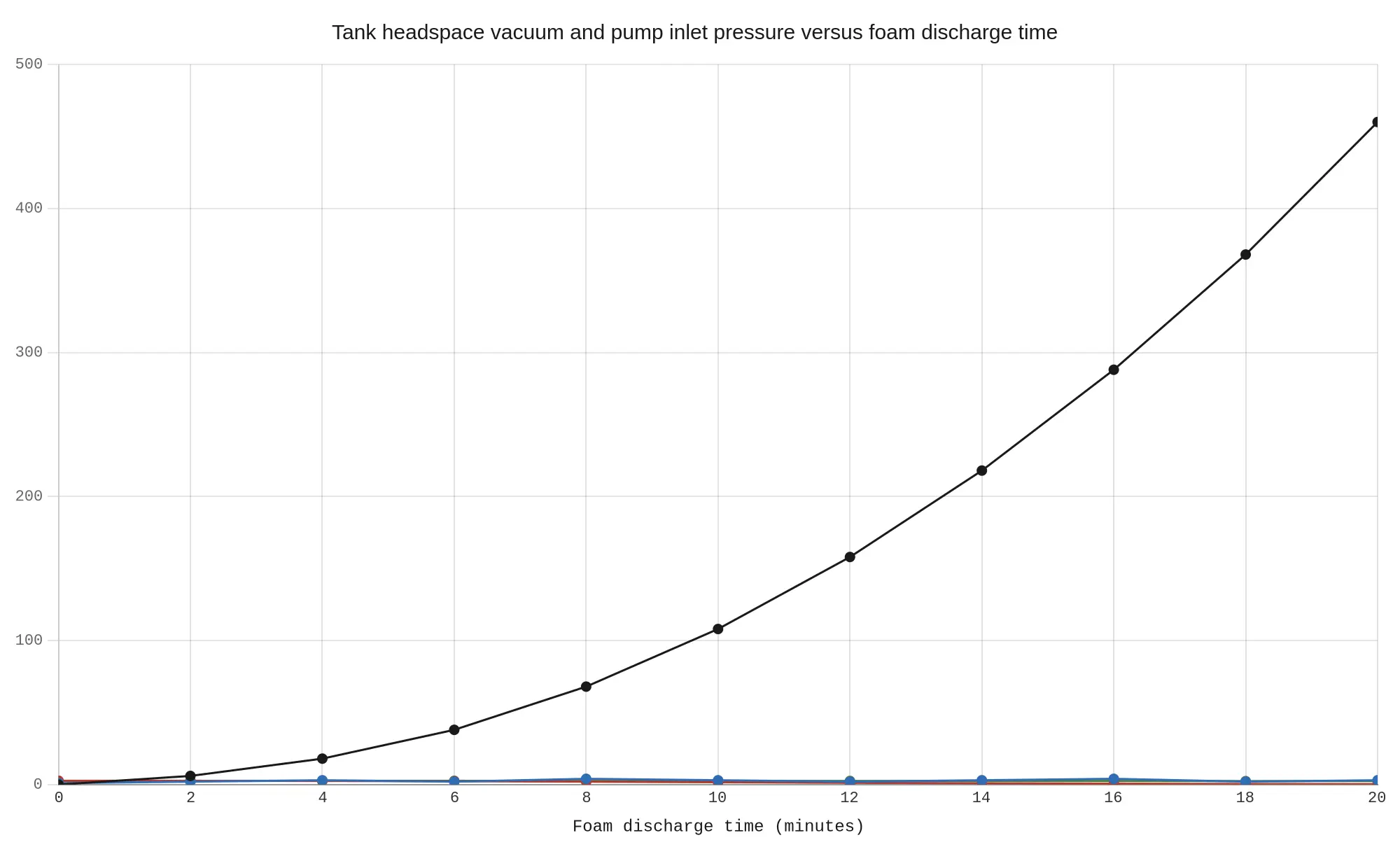
Figure 2. Tank headspace vacuum (left axis, millibar) and pump inlet pressure (right axis, bar) plotted against continuous foam discharge time (0-20 minutes). The blocked-vent traces show headspace vacuum climbing steeply while pump inlet pressure collapses toward cavitation; with a correctly functioning vent, headspace vacuum stays within a few millibar and inlet pressure holds steady. Values are representative engineering values for illustration only and do not represent the test data of any specific vehicle.
For the first few minutes the blocked tank still has enough residual air volume to feed the pump, so the vacuum trace climbs gently and everything on the panel looks normal. Once the pump is moving concentrate faster than air can leak past the stuck valve, the curve bends upward and the inlet pressure trace turns downward: the pump is now being asked to lift liquid with progressively less atmospheric pressure behind it. If inlet pressure is sagging while headspace vacuum is climbing, the vent is the place to look next, not the pump.
Secondary Damage and Downstream Consequences
A stuck foam tank vent valve does not stay a vent problem. Once vacuum holds in the headspace and the pump keeps being asked to deliver concentrate, the fault migrates into castings, seal faces, proportioning logic, and the tank structure itself. Each of the failures below follows from continuing to run a starved suction line.

Cavitation Erosion and Seal Face Distress
When suction pressure falls below the concentrate’s vapour pressure, bubbles form at the impeller eye and collapse as they move into higher-pressure zones, hammering the casting surface until it pits. That pitting is not cosmetic. Erosion at the impeller eye and the volute cutwater changes the flow path, so a pump that was already starved becomes less efficient at recovering pressure even after the vent is freed. On a crash tender foam system, the damage is often discovered only when flow testing shows discharge pressure and volume both short of the rating, long after the vacuum source was corrected.
Vapour pockets forming ahead of the seal chamber strip the liquid film that separates the faces, so they run hot against each other in a mixed vapour-liquid environment. The result is heat checking, face blistering, and a seal that begins weeping concentrate past the gland. This category of pump starvation damage is frequently misdiagnosed as simple seal wear, and a replacement seal fitted without restoring the vent will be destroyed again on the next duty cycle.
Drift, Lost Prime, and Loads the Tank Was Never Rated For
Erratic suction delivery reduces the actual volume of concentrate moved per pump revolution, so the foam proportioning drift develops quietly while the controller still reports its nominal setpoint. Because the foam still looks acceptable on a small test discharge, the error typically goes undetected until annual acceptance testing compares measured expansion ratio and drainage time against the specification.
Vacuum retained in the tank headspace and suction line pulls concentrate back away from the impeller after the PTO stops, allowing air to enter through the least airtight joint in the suction path. The next start runs dry, which is why a foam pump losing prime repeatedly should always trigger a vent inspection before any pump overhaul.
Every re-prime attempt shears air into the agent, and each cavitation cycle keeps agitating it, so repeated aeration works alongside temperature swings to break down the concentrate faster than its rated shelf life. The combined effect on foam quality is covered in the guidance on why temperature swings shorten agent shelf life.
A sustained external pressure differential loads the shell, stiffeners, and weld toes in a direction the tank was never designed to carry, driving fatigue cracking at the seam details. Internal baffles share that load, so baffle cracking and foam tank vent failure often appear on the same vehicle; the weld and baffle failure patterns are described in the article on why water tank baffles crack.
Why a Stuck Vent Valve Starves the Foam Pump
The vent valve is easy to ignore. It has no wiring, no controller, no diagnostic code, and it usually sits high on the tank where nobody looks during a walk-around. Yet it is the only path for air to enter the tank as foam concentrate leaves it. Seal that path and the tank stops being a reservoir; it behaves like a syringe with the plunger held shut.
When the relief poppet or the vacuum breaker disc seizes, headspace pressure drops below atmospheric, a partial vacuum forms, and the pump is asked to lift concentrate out of a vessel that is actively resisting it.
What the valve actually does
A tank vent on a fire apparatus is a two-way breathing device, and both directions matter:
- Spring-loaded relief poppet (outward flow). Cracks open to dump overpressure created by thermal expansion, solar load on a dark tank, filling operations, or concentrate returned during pump recirculation. If it sticks shut, the tank is over-pressured; if it sticks open, concentrate weeps out and the tank breathes continuously.
- Vacuum breaker disc (inward flow). Opens at 20-35 mbar (2-3.5 kPa) of negative pressure to admit air as the pump draws concentrate down. This is the element that fails in the starvation scenario, and the one technicians most often mistake for a solid blanking plate.
- Inlet screen. Keeps dried concentrate skins, polymer crust, insects, and tank debris away from both sealing faces. It is also the single most common place for residue to bridge over and blind the valve completely.
The failure chain, step by step
- The tank is effectively sealed. Either the vacuum disc is glued to its seat by dried concentrate film, ice has formed in the screen or around the disc, or the disc has swollen and jammed in its bore after a fluorine-free foam conversion.
- Headspace pressure falls below atmospheric. Every 10 kPa (about 1.45 psi) of vacuum in the headspace costs roughly 1 m (3.3 ft) of available NPSH at the pump inlet.
- The pump starts to cavitate. A centrifugal foam pump with a modest NPSH requirement is unforgiving; a few psi of tank vacuum is enough to push it past the margin, especially with warm concentrate on a hot ramp.
- Concentrate deaerates and the pump loses prime. Flow becomes intermittent, the discharge pressure gauge chatters, and the pump sounds like it is moving gravel.
- Proportioning drifts and the turret goes lean or dry. The proportioner sees unstable inlet pressure, the ratio wanders, and the finished foam stops being finished foam.
Because the symptoms show up at the pump and at the nozzle, the vent valve is rarely the first suspect. Crews replace pump seals, clean suction strainers, and recalibrate proportioners before anyone climbs up and puts a hand on the vent. If your fault-finding is already pointing at the suction side, the checks in this guide to the causes of a foam pump losing prime pair well with the vent test below.
Quick triage: reading the symptoms
| Symptom on the ramp | What it usually means | First check |
|---|---|---|
| Pump cavitates only when tank level drops | Sealed headspace, vacuum disc stuck | Vent valve inward flow |
| Tank hisses or weeps concentrate at rest | Relief poppet stuck or seal damaged | Poppet seat and spring |
| Hiss or inrush of air when the fill cap is opened | Strong vacuum trapped in tank | Screen and disc face |
| Valve body wet with dried residue | Chronic weep plus crust build-up | Seal condition and screen |
| Fault appears only in cold soak | Ice in screen or around disc | Drain path and heat trace |
Where the valve seizes and where debris hides
Two mechanical interfaces do almost all the failing: the poppet guide stem, which galls or gums up until the poppet cannot lift squarely off its seat, and the vacuum disc bore, where an O-ring or elastomer disc swells in contact with modern surfactant-heavy concentrates and then binds. Residue accumulates in three predictable places: the inlet screen, the seat land where a thin film of dried concentrate cures into a hard lacquer, and the lower spring pocket, which collects concentrate and condensate that never drains. Ice forms wherever that trapped liquid sits, which is why the fault often appears on the first cold morning of the season rather than in the workshop.

Figure 3: Simplified two-dimensional cross-section of a foam tank vent valve. The spring-loaded relief poppet and its guide stem (upper) control outward venting; the vacuum breaker disc (centre) admits air inward as concentrate is drawn; the inlet screen (lower) is where residue and ice bridge first. Both sealing interfaces, not the body casting, are what seize.
Service Procedure: Verifying and Freeing a Stuck Vent Valve
- Depressurise and isolate. Relieve any tank pressure, isolate the tank from the pump, and confirm zero pressure before opening the valve. A relief poppet under a stuck spring can hold residual pressure.
- Inspect the screen first. Remove the screen and hold it to the light. Any bridging film of dried concentrate, polymer skin, or insect debris means the valve has been breathing through a partially blocked path for a long time.
- Test both directions by hand. Gently lift the relief poppet off its seat and press the vacuum disc inward. Both should move freely with light finger pressure and return cleanly. Grittiness or a hard stop is a seizure, not a stiff spring.
- Check cracking pressures with low-pressure air. Feed regulated air to the inlet and watch a low-range gauge. A relief poppet that will not crack within its marked range, or a vacuum disc that needs excessive negative pressure to open, fails the bench test.
- Clean without solvents. Warm water, a soft brush, and a pH-neutral cleaner lift dried concentrate safely. Solvent washes attack the very elastomers that are already marginal, particularly after a fluorine-free retrofit.
- Replace, do not lap. Pitted seat lands, swollen discs, and fretting guide stems are replacement items. Reseating a vent valve seat by hand is not a field repair.
- Address the ice source. If freezing was the cause, verify the drain path is clear, the screen is not holding water, and any heat trace or insulation is intact. Rebuild the valve and it will simply freeze again next season.
- Functional test under draw. With the tank vent refitted and the fill cap closed, run the foam pump at normal output and watch for vacuum using a temporary gauge on the vent port or a spare port in the headspace. A few kPa at full rate is normal; a steady climb toward 10 kPa means the tank is still breathing poorly.
- Record the result. Note cracking pressures, screen condition, and vacuum readings so the next technician can tell deterioration from a one-off blockage.
Never defeat a vent valve to close out a starvation complaint. A blocked-off or permanently open vent converts a pump performance problem into a tank over-pressure or concentrate spill problem, and on an ARFF appliance that trade is never acceptable.
Corrective and Preventive Service Procedure for a Stuck-Closed Vent Valve
The sequence below applies to the atmospheric/vacuum relief vent on an ARFF foam tank and covers both the corrective repair of a valve found stuck closed and the recurring work items that keep it free. Treat every step as a hold point; a vent valve that is freed but not verified will seize again inside one duty cycle.
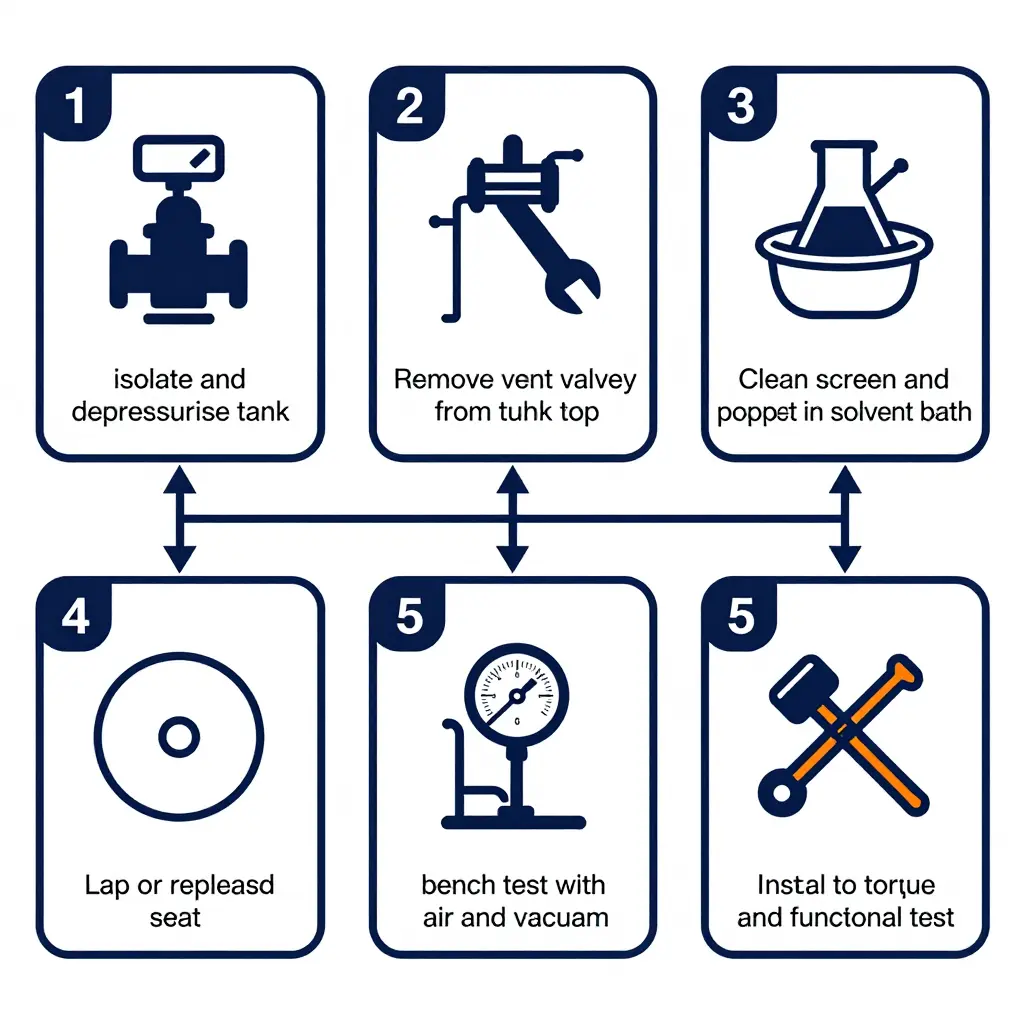
Safe isolation and tank depressurisation
Park on level ground, chock, apply parking brake, shut down the PTO and lock out the pump drive. Isolate the foam concentrate suction and discharge lines and relieve any trapped head. Open the tank fill hatch slowly: a sharp inrush of air confirms the vent is blocked and the tank is under vacuum. Confirm 0 kPa on the tank gauge and allow the ullage to equalise for a minimum of five minutes before disturbing the vent body. Full PPE, including face shield and chemical gloves, is mandatory because residual concentrate in the vent housing is corrosive and slippery.
Removal sequence
- Clean the valve exterior and note the installed orientation, port direction and arrow marking.
- Crack the retaining fasteners in a cross pattern, then remove them evenly to avoid distorting the flange.
- Lift the valve body and gasket as one assembly and immediately cap the tank boss to prevent foreign object ingress.
- Bag and tag the valve; never let it rest in spilled foam residue, which will set in the screen.
Cleaning foam residue without damaging the screen
Soak the valve in warm water not exceeding 40 °C with a mild alkaline detergent or the concentrate manufacturer’s approved cleaner. Do not use aggressive solvents, caustic dips, wire brushes or high-pressure jets; these attack EPDM/FKM seals and deform the fine mesh. Work the screen with a soft nylon brush, back-flush from the clean side, and use ultrasonic cleaning where available. Rinse with demineralised water and air-dry; never blow compressed air directly across the mesh.
Seat lapping and replacement criteria
Lap only light witness marks, using 400-600 grit on a flat plate, and remove no more than 0.05 mm (0.002 in) of seat material per service. Replace the seat assembly if groove depth exceeds 0.2 mm, if seat width varies by more than 20 percent, or after two lapping operations. Replace the screen if more than 10 percent of the mesh area is blocked or any tear is visible under backlight. All elastomers are single-use once disturbed.
Spring free-length and cracking-pressure verification
Measure spring free length with a caliper against the nominal figure; reject any spring shorter than 97 percent of nominal or showing a permanent set greater than 2 percent. Verify cracking pressure on the bench rather than by feel, and record the value against the nameplate.
Bench test acceptance criteria
| Parameter | Test method | Acceptance |
|---|---|---|
| Cracking pressure | Slow air ramp, rising | Within ±10 percent of nameplate |
| Reseat point | Slow bleed down | Closes within 20 percent below cracking |
| Pressure leak-down | Hold at 1.5x cracking, soap test | No continuous bubble for 60 s |
| Vacuum opening | Slow vacuum ramp | 2.0-3.5 kPa (8-14 in H2O), typical |
| Vacuum leak-down | Hold at 1.5x vacuum opening, 5 min | Less than 1 kPa loss |
| Spring free length | Caliper | 97 percent of nominal minimum |
| Screen condition | Visual, backlit | Less than 10 percent blocked, no tears |
Confirm final acceptance values against the OEM manual; where the manual is silent, use the table above as the baseline for vacuum relief valve testing. A valve that opens but leaks down has not passed.
Condensate removal and freeze protection
Drain the low point of the vent housing and the tank sump at every service. In freezing climates, verify heat trace and insulation continuity, confirm the drain port sits at the lowest point after reinstallation, and drain the vent after washing. Ice in the pilot port is a common cause of a vent valve stuck closed in winter, and it presents identically to a foam-fouled screen.
Reinstallation torque and orientation
Fit a new gasket, apply no sealant on the seating face, and torque in a cross pattern in two stages to the OEM figure (typically 20-24 Nm for M8 fasteners). Fit the valve with the vapour port up and the drain slot at the low side, arrow aligned to the flow direction. Paint, thread tape and excess sealant must not enter the bore.
Functional test after refilling
Refill at the maximum permitted rate and watch the tank gauge; the vent must relieve smoothly with no pressure spike. Then run the foam pump at rated flow and confirm no vacuum develops in the tank and no cavitation signature appears at the pump. If vacuum returns or the pump still starves, re-inspect the vent and the tank-to-pump path together rather than assuming the valve is at fault.
Preventive maintenance intervals
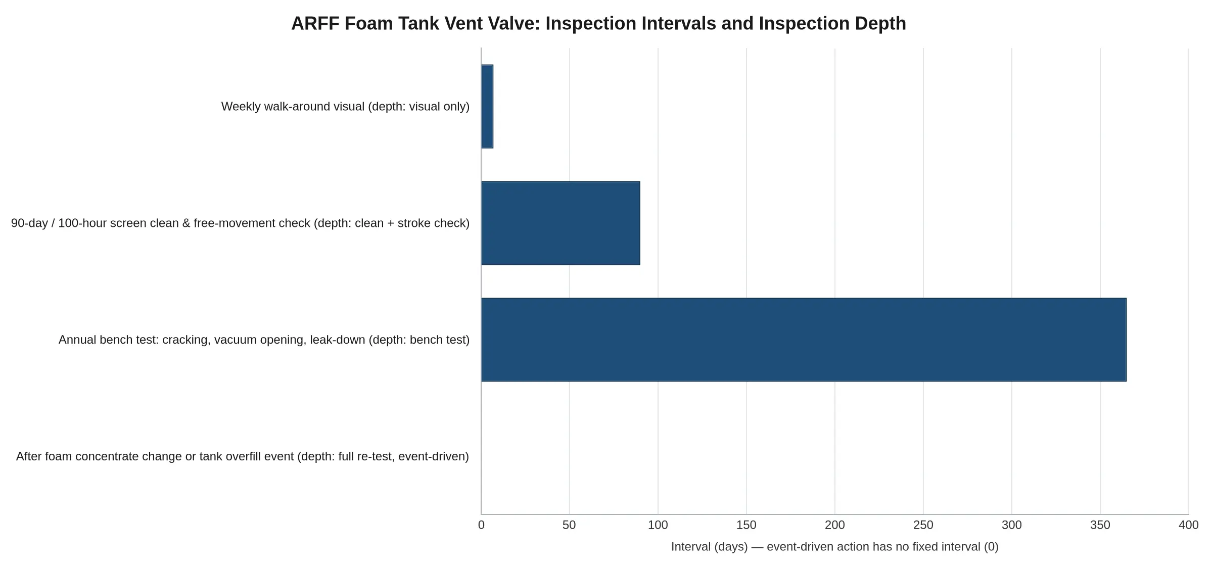
Add the vent to the ARFF preventive maintenance schedule as follows: visual free-movement and debris check weekly; screen clean and poppet stroke check at 90 days or 100 operating hours, whichever comes first; full bench test annually; and an unconditional re-test after any concentrate change, tank overfill, fluorine-free retrofit or foam spill over the tank top.
Foam residue makes this a recurring item because concentrate is formulated to form a persistent film. Every fill, overflow and proportioning cycle wets the vent screen and poppet; the film dries to a sticky layer, crystallises at the edges, bridges the mesh and glues the poppet to its seat. The valve is a consumable in practice, not a fit-and-forget component.
A repaired or replaced vent valve is still an unproven component until it has been put back under the conditions that exposed the fault. Work through the following checklist in order; the vehicle is not released until it has passed the scenario that pulled vacuum on the tank.
Recommissioning checklist
- Verify vent free movement. Stroke the vent valve manually from fully closed to fully open and confirm the disc or poppet travels the complete stroke with no binding, no stick-slip, and less than 2 N of hand force at every point.
- Confirm screen fitted. Confirm the spatter screen is seated flat in the vent body with the retaining ring fully engaged and no gap exceeding 0.5 mm anywhere around its perimeter.
- Refill and confirm no vacuum at idle. Refill the foam tank to its normal working level, start the engine, and confirm headspace pressure at idle sits within ±0.5 kPa of ambient on a calibrated manometer.
- Run discharge at rated flow while monitoring headspace vacuum. Open the tank-to-pump line and discharge at the vehicle’s rated foam solution flow for a full five minutes, confirming headspace vacuum never exceeds the manufacturer’s limit (typically 2 kPa, about 8 in. of water).
- Confirm proportioning rate against the acceptance tolerance. Sample the solution at the turret with a calibrated conductivity meter and confirm the proportioning rate holds within the acceptance tolerance – commonly ±10% of the set value, so 2.7% to 3.3% for a 3% setting – across the full flow range. This is the step that catches the slow foam proportioning drift that goes undetected on the ramp.
- Inspect for concentrate seepage at the valve. Inspect the valve body, flange faces, and screen retaining ring for concentrate seepage and confirm the assembly is dry to the touch with zero droplet formation after 30 minutes under pressure.
- Record readings on the maintenance record. Log the headspace vacuum, measured proportioning percentage, and discharge flow rate on the vehicle maintenance record, ensuring every value is legible, signed by the technician, and annotated with the serial number of the instrument used.
- Return the vehicle to service status. Release the vehicle by clearing the out-of-service tag, updating the fleet status board, and obtaining a supervisor signature on the completed record.
The functional test only counts as a pass when all eight conditions are documented. If any single reading falls outside tolerance, the vehicle stays out of service and the sequence restarts at step 1.
Where Vent-Related Starvation Really Comes From
Once the checklist has confirmed that vacuum rather than a worn impeller or a mis-set relief valve is starving the pump, the next question is what caused it. Across the vent, screen and hose assemblies that feed an ARFF foam tank, the failure modes fall into two groups that need different responses: obstructions in the air path, and worn or misadjusted components.
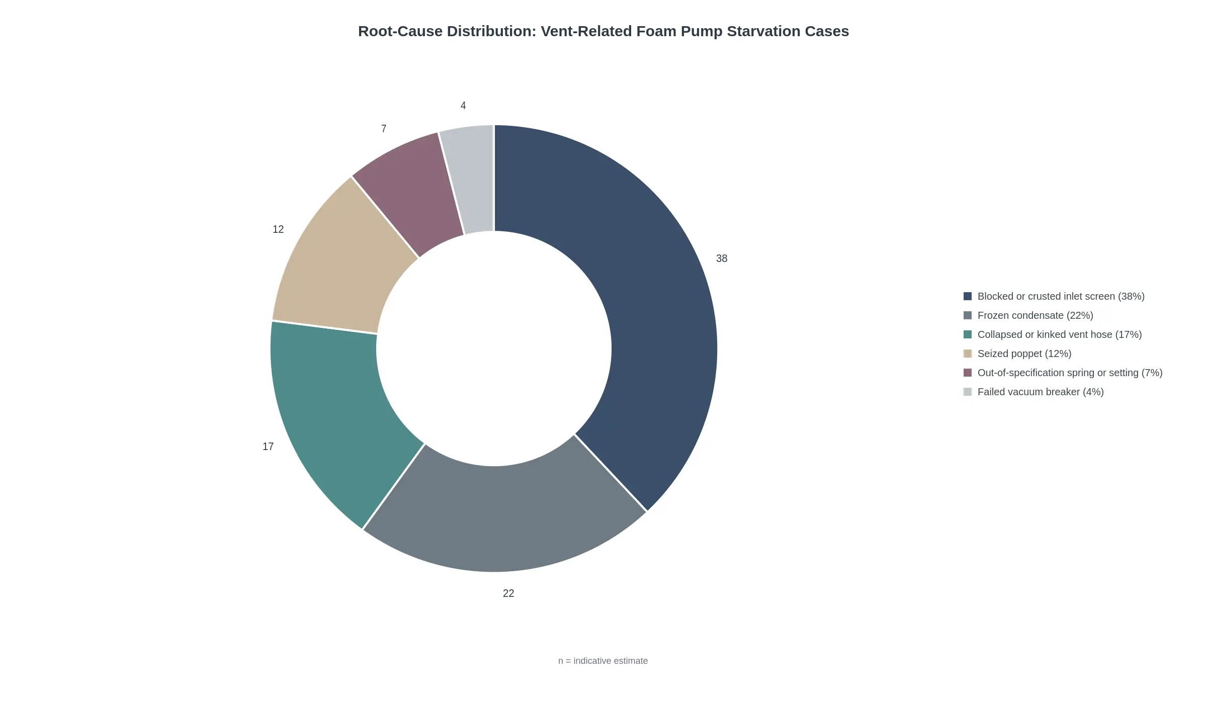
Figure: Root-cause distribution in vent-related foam pump starvation cases. Figures are indicative engineering estimates compiled for training and diagnostic orientation, not the output of a formal fleet survey. Treat the shares as a starting hypothesis, not a benchmark.
The ring is an allocation of the failure modes described in this article, not counted field data, and no maintenance decision should rest on the exact percentages. What it illustrates is a question worth asking in a maintenance meeting: are you spending hours on components, or on the air path?
Why the blockage share matters
A crusted screen is a cleaning problem. Frozen condensate is a drain-and-dry problem. A kinked hose is a routing and handling problem. All three are solved by a regime, not by a parts order: scheduled flushing, screen inspection, moisture control in the vent line and physical protection of the hose run, rather than a replace-on-suspicion habit that swaps good hardware and leaves the root cause in place.
The poppet, spring and vacuum breaker still deserve attention, but they should be tested after the vent path is proven clear. If you are seeing intermittent starvation that clears itself on the next run, work through the sequence in our analysis of why an ARFF foam pump loses prime before condemning valves.
Chart data and configuration
The shares are repeated in the table below for screen readers and print, then rendered by the Chart.js configuration that follows.
| Root cause | Share (indicative) | Category |
|---|---|---|
| Blocked or crusted inlet screen | 38% | Obstruction |
| Frozen condensate | 22% | Obstruction |
| Collapsed or kinked vent hose | 17% | Restriction |
| Seized poppet | 12% | Component wear |
| Out-of-specification spring or setting | 7% | Component wear / adjustment |
| Failed vacuum breaker | 4% | Component wear |
const ventCauseChart = new Chart(document.getElementById('ventRootCause'), {
  type: 'doughnut',
  data: {
    labels: [
      'Blocked or crusted inlet screen (38%)',
      'Frozen condensate (22%)',
      'Collapsed or kinked vent hose (17%)',
      'Seized poppet (12%)',
      'Out-of-specification spring or setting (7%)',
      'Failed vacuum breaker (4%)'
    ],
    datasets: [{
      label: 'Share of cases',
      data: [38, 22, 17, 12, 7, 4],
      backgroundColor: ['#3B4F6B', '#6E7B85', '#4F8A8B', '#C9B79C', '#8C6A7A', '#BFC5C9'],
      borderColor: '#FFFFFF',
      borderWidth: 2
    }]
  },
  options: {
    responsive: true,
    cutout: '52%',
    layout: { padding: { top: 18, right: 34, bottom: 34, left: 34 } },
    plugins: {
      legend: { position: 'right', labels: { boxWidth: 10, boxHeight: 10, padding: 9 } },
      title: {
        display: true,
        text: 'Root-Cause Distribution: Vent-Related Foam Pump Starvation Cases',
        color: '#2F3A45'
      },
      subtitle: {
        display: true,
        position: 'bottom',
        text: 'Indicative engineering estimates for training purposes, not survey data',
        color: '#6B7280'
      },
      datalabels: {
        display: true,
        anchor: 'end',
        align: 'end',
        offset: 10,
        clamp: true,
        color: '#2F3A45',
        formatter: (value) => value + '%'
      }
    }
  }
});
Load chartjs-plugin-datalabels after Chart.js for the labels to appear; without it the ring still renders and the legend carries the values. For print export, set devicePixelRatio to 2 before rendering so the white segment borders stay crisp at small sizes.
Foam Tank Vent FAQ: Vacuum Limits, Valve Testing, and Service Intervals
Short answers to the questions that come up when an ARFF foam tank pulls vacuum, a proportioner leans out, or a vent valve is suspected of being stuck.
Why does my foam tank pull vacuum, and how much vacuum indicates a blocked vent?
A healthy tank headspace sits within about 0.1 psi (2.8 inH2O) of atmospheric during a full pump draw. Past the typical 2 kPa (0.3 psi) acceptance limit the vent is already suspect, a steady 0.5 psi or more of negative pressure confirms a restriction, and 1 psi or more indicates a blocked vent. Confirm on a gauge tee’d into the headspace line, not the suction line, because suction vacuum reads plumbing restriction rather than vent restriction.
Can a blocked vent starve the foam pump?
Yes. Once the vent blocks, the pump removes concentrate faster than the headspace can backfill, so tank pressure falls below the pump’s inlet requirement and the impeller cavitates. Flow decays, discharge pressure oscillates, and the proportioner leans out before the pump sounds dry. A collapsed suction hose produces the same pattern, so rule out both, plus the faults behind a foam pump that keeps losing prime, before condemning hardware.
How do I test a foam tank vent valve, and can a stuck valve be diagnosed from the cab?
Bench-test the valve off the tank with a low-pressure gauge and a hand vacuum pump: it should relieve within its stamped cracking value, typically 0.5 psi vacuum. In service, tee a gauge into a spare headspace port and draw concentrate at rated flow; vacuum that climbs with flow points at the vent. From the cab you get only indirect evidence, suction gauge movement and flow decay, because there is no vent-specific indication on the panel. Confirm at the tank.
Can the vent be temporarily opened to complete a call-out?
Only as a documented emergency expedient on an active incident: remove the vent element or crack the headspace fitting so the tank draws atmospheric air through a clean opening, complete the response, then restore the assembly before the appliance returns to service and log a deferred defect. Do not leave it open; sloshing concentrate escapes and ramp debris enters the headspace. This is a way out of a call, not a fix for a chronic complaint, and a vent that weeps or passes concentrate under normal draw is failed, not adjusted.
How does a stuck-open valve differ diagnostically from a stuck-closed one?
A stuck-closed valve produces negative headspace pressure, cavitation, flow decay, and a pump that recovers when the tank is manually vented. A stuck-open valve produces no vacuum at all, but leaves concentrate residue weeping from the vent, wet staining down the tank side, moisture ingress into the headspace, and a tank that siphons or overflows when filled. Residue direction, not gauge reading, separates them fastest.
How often should the vent be inspected in high-humidity or coastal environments, and does fluorine-free residue change that?
The baseline is the schedule above: weekly free-movement check, screen and stroke at 90 days or 100 hours, bench test annually. Coastal and high-humidity operations should shorten the screen and stroke interval rather than wait for the 90-day mark, because salt aerosol and constant condensation corrode the relief spring and disc and crystallise in the mesh. Fluorine-free concentrate changes the interval again: its residue films and crystallises on the disc and screen, so clean the vent after any discharge that wets the tank top and function-test it at every service.
Consolidating the Chain: Vent, Vacuum, Starvation
A stuck or blocked airport crash tender foam tank vent seals the tank, so every litre the pump draws out has to be replaced by something, and with no air permitted in, that something is vacuum. As tank pressure falls below atmospheric, suction lift climbs, the inlet line cavitates, and concentrate arrives at the proportioner in slugs rather than a steady stream. The visible outcome is a pump that sounds starved, a foam blanket that surges and collapses, and a fault blamed on the pump, the proportioner or the concentrate rather than on a small, partly seized valve. Because that end state is easy to misread at the panel, it is worth pairing this with a look at foam pump losing prime to see how the symptom presents before any component is condemned.
An ARFF fleet maintenance programme that keeps this fault rare does four things as routine work rather than as reactions:
- Vent inspection on a fixed interval. Check free movement, corrosion, foam residue and insect or ice blocking, and record the result against the vehicle rather than against memory.
- Recorded vacuum readings during functional tests. A number written down at every test turns an invisible drift into a trend line you can act on.
- Spring and screen verification at rebuild. Confirm cracking pressure and clean mesh before the tank goes back into service, not after the first live run.
- Operator reporting of unstable foam flow. Crews notice spitting and surging long before a gauge does, provided the report has somewhere useful to go.
CIMC Fire Rescue supplies ARFF equipment, from proportioning hardware through to turret systems, and also delivers vehicles, station buildings and the services around them, so a fleet can be specified, commissioned and supported through one supplier (cimcfirerescue.com).
The diagnostic principle outlasts the individual repair: a tank that cannot breathe will always take its displacement out of the pump. Establish whether the tank is breathing before rebuilding anything downstream of it.