Why the Control Link Fails Before the Heat Gets Close

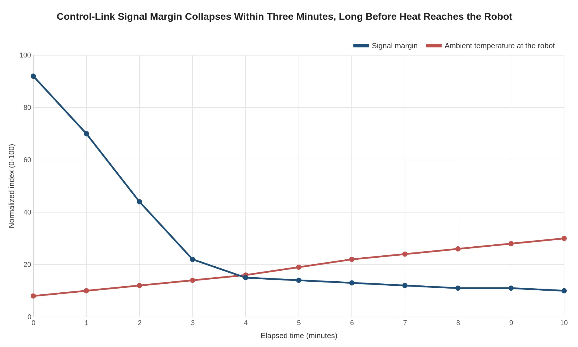
Send a firefighting robot into a substation fire and its control link usually drops before flame or radiant heat reaches the machine. The substation attacks signal integrity far faster than it attacks structure, so the link is the first subsystem to go.
Four terms recur throughout this piece. A firefighting robot is an unmanned ground vehicle that carries a monitor or nozzle and is driven from outside the hazard zone. Teleoperation is how it is driven: a person at a console sends movement and stream commands, and the machine sends back video, position and telemetry. A substation fire is a fire involving transformers, switchgear, busbars, insulators or cable trenches, where very large amounts of electrical energy sit in a small footprint. The control link is the whole communications chain that carries those commands and that video: the robot’s radio and antenna, the data path, the receiving station and the software at both ends.
Why the link gives out first
The robot is built to survive heat. Its structure, hose, turret and tracks are designed around time and temperature. The control link is designed around something more fragile, a clean signal, and the two fail on very different clocks. Structural damage usually takes minutes. Signal damage starts in milliseconds.
What attacks the signal before the fire does
Fault current, switching operations and arcing inject electromagnetic interference into the air and into every cable on site. Ground potential rise pushes the local earth reference away from the reference the radio and its electronics expect. Arc transients arrive as broadband spikes that swamp receivers, and smoke, steam and heat plumes refract and scatter the radio path itself. Electronics that are warm rather than burnt drift out of tolerance too: oscillators shift frequency, amplifiers lose gain, packet loss climbs before anything visibly fails.
None of this requires the fire to touch the robot. Standing inside an electrically hostile field is enough, and the machine does that from the first minute, so one that still looks undamaged can already be out of control. Where the robot sits and how it talks home decide more than the fire does. Settle which fireground tasks actually justify a firefighting robot before committing to a layout.
The three failure channels
Damage reaches the link through three families of failure:
- Electromagnetic interference – radiated and conducted noise from arcing and switching that overwhelms the radio path and the data cable.
- Ground potential rise – a shifting earth reference that corrupts the signals and references the electronics rely on.
- Thermal drift in electronics – gradual, quiet loss of radio and processor performance from heat that has not yet damaged anything visible.
Cable decay and power-supply faults belong in the same picture, and the next section takes all five mechanisms in turn.
Interference and Grounding: How the Link Actually Fails
When the link drops at a substation fire, the instinct is to blame the flames. Most of the time the cause is electrical, and it is present long before radiant heat matters. Five mechanisms account for most failures, and each runs the same way: a physical cause, an effect on the link, and a symptom an operator can see from the console.
Broadband noise from switching and arcing
Cause: Contactors, variable-frequency drives, welding arcs and arcing fault current radiate and conduct wideband energy from tens of kilohertz to gigahertz.
Effect on the link: The receiver noise floor rises, packets fail checksums, retries climb and usable throughput falls until the link times out.
Observable symptom: Video stutters or drops the instant pumps, tools or switchgear energise, then recovers when the load stops. Link quality is fine at idle and collapses under work.
Earth-grid potential rise: common-mode voltage
Cause: Fault current returning through the substation earth grid develops a voltage difference between grounding points, governed by grid resistance and fault current magnitude. Any two grounded ends of one signal cable sit at different potentials.
Effect on the link: That difference appears as common-mode voltage and ground-loop current on the signal pair, exceeding what the transceiver can reject and injecting transients into the front end.
Observable symptom: Dropouts coincide with faults or heavy load switching rather than with temperature; the link reconnects unpredictably, and error logs cluster around ground-current events.
Shield and connector decay
Cause: Repeated deployment flexes cable, chafes it against hard points and lets moisture and dust into connectors. A shield terminated with a long pigtail, or a crimp gone high-resistance, stops working without announcing it – the same failure family seen in wiring harness and cable chafe.
Effect on the link: Shield coverage and transfer impedance degrade, so external noise couples directly into the signal pair and attenuation rises.
Observable symptom: A machine that worked on a clean apron becomes unreliable in an electrically noisy yard, with rising error rates across successive deployments and faults that move when the connector is wiggled.
Power-supply ripple: starving the radio module
Cause: Switch-mode ripple, pump and motor start currents, long DC cable runs and sagging batteries all ride on the supply feeding the radio module.
Effect on the link: The module’s supply dips below regulation, its oscillator drifts, transmitter power sags, and the processor may brown out and reset mid-session.
Observable symptom: Signal strength drops with no change in distance, the module reboots or relinks, and dropouts line up with current peaks rather than with radio distance.
Thermal derating below flame temperature
Cause: Battery packs and radio electronics begin derating at ambient temperatures of roughly 45-60 °C, well under the temperatures that damage steel or ignite a structure.
Effect on the link: Available transmit power, clock stability and runtime shrink, so range and throughput fall while the machine itself still looks operable.
Observable symptom: Range that was adequate on a cool morning becomes marginal on a hot day or after a long idle in the sun, and recovers once the unit cools.
| Observable symptom | Most likely mechanism |
|---|---|
| Drops when pumps start | Ripple or broadband noise |
| Drops during a fault | Earth-grid potential rise |
| Degrades over many deployments | Shield and connector decay |
| Range falls with no distance change | Ripple or derating |
| Fails in warm ambient, recovers cold | Thermal derating |
What this means when you specify equipment
Ask vendors for shielded cable with 360-degree shield termination, single-point grounding, isolated transceivers, ripple-tolerant power conditioning, redundant or diverse links, and published thermal derating curves. A link that survives the electrical environment is still working when the fire gets close, and that window is the one an operator cannot get back.
Control-link failure modes: mechanism, first symptom, design countermeasure
| Failure mode | Underlying mechanism | First observable symptom | Design countermeasure |
|---|---|---|---|
| Electromagnetic interference | Radiated and conducted noise from VFDs, radios, and welding arcs couples into analog and digital control lines | Random command dropouts, spurious E-stop trips, jerky actuator motion | Shielded twisted-pair cable, ferrites, filtered connectors, spread-spectrum switching |
| Ground potential rise | Fault current lifts earth potential between the substation grid and the robot chassis; current flows through cable shields | Comms errors across all channels at once, control voltage offset, blown shield bonds | Single-point bonding, isolated CAN transceivers, fiber-optic links, equipotential mat |
| Connector and cable degradation | Vibration, heat cycling, UV exposure, and foam residue corrosion at pins | Rising contact resistance, recurring link resets, green or pitted pins at inspection | Sealed IP67 connectors, strain relief, dielectric grease, scheduled resistance checks |
| Thermal drift of electronics | Gain, offset, and oscillator frequency shift as the enclosure heats up | Slow disagreement between redundant channels, timing jitter, added latency | Temperature compensation, thermal isolation, derated components, active cooling |
| Power and battery supply instability | Voltage sag from load spikes, aged batteries, alternator droop under idle | Brownout resets, dimming indicators, channels dropping out under load | Wide-input DC-DC converters, supercapacitor or UPS buffer, low-voltage disconnect alarms |
| Moisture and contamination ingress | Steam, condensation, and foam pushed past aging seals into junction boxes | Intermittent leakage current, nuisance ground-fault trips, fogged housings | Pressurized enclosures, breathable vent membranes, potted boards, seal replacement intervals |
Early Warning Indicators of a Degrading Control Link
The link usually signals that it is struggling well before flames reach the apparatus. The list below works as observation points on the fireground, and as questions for procurement teams to put to vendors: how is each one logged, alarmed and reported to the operator?
- Rising latency – round-trip commands stretch from steady to erratic, the earliest sign of a fading control link.
- Intermittent video frame loss – the feed stutters or freezes while audio and telemetry keep running fine.
- Command acknowledgment delays – the robot moves a beat late, or re-executes a command you already cancelled.
- Packet retries climbing – the radio keeps resending the same instruction because confirmation never arrives.
- Signal-strength fluctuation – RSSI swings sharply as the unit moves behind walls, tanks or steel structures.
- Actuator response lag – nozzle, arm or drive inputs land seconds after the operator’s stick movement.
Turning Indicators Into Decisions
One blip is noise. Two or three appearing together is a pattern, and the pattern is the window to reposition the robot, shorten the run or switch to a fallback control path before the link drops altogether. Buyers should insist on dashboards that trend these values over the whole mission, not a five-bar signal icon.
Control-Link Path and Interference Sources

Figure 1. The link is three blocks long, and every interference source in the diagram feeds into it rather than into the fire. The drop usually starts where the blocks meet: noise coupling into the radio, a ground-potential offset across the tether, or heat degrading the electronics while the flames are still far off.
Specification and Mitigation Guidance: Making the Control Link Survive the Yard
Most control-link failures at a substation fire are decided long before the fire, in a tender document that never asked about them. Buyers specify reach, flow rate and camera resolution, then leave the communications architecture to the supplier’s standard catalogue, and the machine that worked in the demo yard goes quiet beside an energised 132 kV busbar.
What follows is written as what to specify and what to witness, not what to buy. It assumes the earlier question is settled: what the machine is for, as set out in this piece on which fireground tasks actually justify a firefighting robot. A link that carries video to a spotter needs far less redundancy than one metering foam into a live switchyard.
Reference Table 1: Electromagnetic compatibility clauses for the tender
Refuse “designed to industrial standards” as a written answer. Name the tests, the levels and the evidence.
| Parameter | Specify | Acceptance evidence |
|---|---|---|
| Radiated immunity | IEC 61000-4-3, 20 V/m, 80 MHz to 2 GHz, 80% AM at 1 kHz | Accredited test report on the full control package |
| Conducted immunity | IEC 61000-4-6, 10 V rms, 150 kHz to 80 MHz | Report including the radio feed cable |
| Fast transient burst | IEC 61000-4-4, level 4: 4 kV on power ports, 2 kV on signal ports | Report plus in-vehicle retest |
| Surge | IEC 61000-4-5, 2 kV line to earth on the link cabling | Report |
| Electrostatic discharge | IEC 61000-4-2, 8 kV contact, 15 kV air | Report, enclosure and connector faces |
| Power-frequency magnetic field | IEC 61000-4-8, 100 A/m continuous | Report, worst-case cable routing |
| Pulsed magnetic field | IEC 61000-4-9, up to 1000 A/m | Report, switchgear proximity |
| Damped oscillatory | IEC 61000-4-10 damped oscillatory magnetic field at 100 kHz and 1 MHz; IEC 61000-4-12 ring wave | Report |
| Comms equipment rating | IEEE 1613 or IEC 61850-3 for any switch, gateway or media converter | Certificates |
| Emission | CISPR 11 Class B rather than Class A, so emissions do not disturb protection equipment nearby | Report |
Two practical additions belong in the same clause: a witnessed functional test with the machine parked beside live switchgear, and a declaration of the field strength at which the link first degrades.
Reference Table 2: Signal path construction
| Requirement | Specify |
|---|---|
| Long runs | Fibre only for any path leaving the vehicle envelope or crossing the yard |
| In-chassis runs | Shielded twisted pair, 360 degree gland termination, screened connector shells |
| Separation | Minimum 300 mm from 400 V and from CT and VT circuits, right-angle crossings only |
| Shielding | Single-point screen earth at the radio end, documented, no double-earthed screens |
| Mechanical protection | Armoured, rodent-resistant, crush-rated conduit, splice-free runs, accessible test ports |
| Termination | Field-serviceable connectors, no sealed overmoulds on the link backbone |
Cable faults rarely announce themselves. A screen that is gradually lost, a jacket chafed behind a clip, a connector that has taken three years of washdown: the same pattern documented in this analysis of wiring harness chafe issues on crash tenders, and it looks identical from the operator’s seat, an intermittent link that resets whenever the chassis flexes.
Reference Table 3: Redundant and diverse channels
| Element | Specify |
|---|---|
| Diversity | Two channels on different media, for example fibre plus licensed or unlicensed radio |
| Routing | Physically separate ducts, no shared trench, no shared cabinet entry, no shared connector block |
| Power | Each channel on its own supply and its own protection device |
| Failover | Automatic switchover within 500 ms, no operator action, no reboot |
| Monitoring | Continuous heartbeat on both channels, health shown on the operator display |
| Proof | Factory demonstration with each channel cut in turn and both cut together |
Redundancy that shares a conduit, a fuse or a switch is not redundancy. Write the definition into the specification instead of assuming it.
Reference Table 4: Thermal derating margins for on-board electronics
| Specified margin | Value to state |
|---|---|
| Design ambient at the enclosure | 55 C continuous, 60 C survival, measured not assumed |
| Internal air rise | No more than 15 K above external ambient at full load |
| Component headroom | At least 15 C between rated maximum and worst-case calculated junction |
| Electrolytic capacitors | 105 C rated parts, derated to no more than 50% of rated ripple at 70 C |
| Enclosure finish | Light colour, solar standoff or shade, no unvented black boxes in direct sun |
| Cooling failure | Link must stay up for 30 minutes with the fan failed |
| Verification | 8 hour soak at 60 C with the link running error-free, logged |
Solar gain is usually the culprit, not air temperature. A sealed box reading 60 C in 30 C weather is an ordinary finding on a machine parked in an open yard.
Reference Table 5: Monitored battery and power architecture
| Requirement | Specify |
|---|---|
| Architecture | Dual feed, main bus plus independent battery bus for control and comms |
| Autonomy | 30 minutes minimum for the control link, sensors and radio with the engine stopped |
| Battery management | Per-cell or per-block voltage, temperature, state of charge and state of health reported live |
| Alarms | Low voltage, over-temperature and capacity fade flagged before the link degrades, not after |
| Load shedding | Documented order, link and sensors retained last, turret and lighting shed first |
| Charging | Temperature-compensated charger with remote sensing at the battery terminals |
| Disconnect | Defined low-voltage disconnect that protects the link rather than the starter motor |
The battery should be a monitored subsystem with a data trail, not a black box that reveals its condition by failing.
Reference Table 6: Fallback behaviour when the link drops
| Trigger | Specified behaviour |
|---|---|
| Heartbeat lost, 500 ms | Hold last valid command, no new motion acceleration, turret decelerates |
| 2 seconds | Controlled stop, pump to neutral, valves closed, park brake applied |
| 10 seconds | Safe state, boom and turret stowed, beacon on, continuous self-monitoring, no discharge without a fresh command |
| Link restored | Re-acquire only after positive operator confirmation, never automatic motion resume |
| Loss beyond 30 minutes | Engine to idle then shutdown, fault logged, beacon maintained |
| Override | Physical emergency stop on the vehicle, independent of the link, reachable by a person at the machine |
Require the supplier to hand over the state machine in writing and to demonstrate every row above in a dry run, with the link severed at the harness and, separately, at the antenna. The battery master switch and parasitic drain belong in the same acceptance walk-round.
Writing it into one scope
CIMC Fire Rescue supplies the vehicle, the control architecture and the field service behind it as one equipment and service package. The clauses above cross mechanical, electrical and software boundaries that otherwise get argued between three suppliers, and the party who signs the acceptance test should be the party who answers when the link drops at 3 a.m.
Every clause above needs a witnessed test behind it, including the failure cases. A link that has never been deliberately cut is still an assumption.
FAQ: Control Link Behaviour at a Substation Fire
Why does the control link drop before heat reaches the substation fire?
Radio energy fails in a substation long before temperature rises. Steel, copper busbars and earthed metal cladding absorb and reflect the signal, and smoke and water spray from the monitor streams add attenuation on top. The control link therefore degrades on interference and geometry rather than on heat. A firefighting robot driving behind switchgear or into a cable trench is out of effective range while the flames are still tens of metres away, so treat signal loss as the first warning, not as a heat-related failure.
How far can a firefighting robot normally operate from its command post?
Most tracked firefighting robots hold a reliable control link at roughly 300 to 500 metres in open, line-of-sight conditions. Inside a live switchyard, with metal-clad cabinets, transformer banks and steel lattice in the path, that figure typically falls to 100 to 200 metres, and sometimes under 100 metres behind a large transformer. Brochure figures assume clear sightlines, so plan the command post position around the obstructions rather than around the maximum number.
Does a tether solve the problem?
A tether gives a data path the radio cannot guarantee, so it removes the unpredictable drop-outs. It brings its own constraints: travel is limited to the drum length, the cable can snag on debris or kerbs, someone has to manage the reel, and the jacket can be damaged by radiant heat or run over. Use it as a deliberate fallback for high-interference zones rather than a full replacement for radio, and check that the reel length covers the positions you actually intend to occupy.
How can we test link robustness before purchase?
Run a spectrum survey at the site and walk the intended attack route with a test transmitter, logging signal strength and packet loss at each stop. Ask the vendor for real RSSI logs, reconnection times and behaviour under simulated smoke and water spray, then repeat the trial with the robot at full working height. Our guide to which fireground tasks actually justify a firefighting robot helps you define those test positions before you shortlist units.
What happens to the robot when the link is lost?
Well-specified machines run a watchdog timer. When telemetry stops, the robot halts movement and holds nozzle position, then applies the fallback on the timer’s schedule: some designs put the pump to neutral within two seconds, others hold the last commanded pattern for the full timeout before shutting down. Many then run a pre-set posture, either holding in place with strobes active, reversing along the recorded path, or returning to the last known good waypoint. Ask for that sequence in writing, with the timeout value and whether an operator can override it, because the answer decides what the crew has to manage if the link never comes back.
The Decision Framework: Buy for Link Integrity, Not Heat Tolerance
For a substation fire response, the finding that matters is this: control-link integrity, not thermal robustness, is the binding constraint. Robots that survive the heat routinely fail the mission because the command-and-telemetry path collapses first – under reflected RF in a steel-and-concrete yard, under electrical noise, or behind a switchgear wall. Thermal margins can be quantified, tested and covered with shielding and standoff distance. A link that drops as the machine enters the yard cannot be recovered afterwards. The requirements below exist to make that failure mode visible before you sign.
What to demand in the technical specification
- A stated link budget with an explicit fade margin measured against a substation noise floor, not an open-field figure.
- Protocol, frequency band, duty cycle, end-to-end latency and telemetry update rate, given as numbers with tolerances.
- The defined fail-safe posture on link loss: hold position, stop, retract, or continue autonomously – and the hold time before each action.
- Antenna diversity, shielded and separately routed cabling, and EMC qualification to a named standard.
- Independent power for link electronics, with backup runtime stated in minutes.
- Declared operating range with obstruction and reflection present, plus the conditions under which that range was verified.
Acceptance tests to witness
| Test | What it proves | Pass criteria |
|---|---|---|
| In-position RF survey | Real range in a reflective yard | Documented margin at the farthest working point |
| Deliberate link-loss injection | Fail-safe timing | Robot reaches safe state within the specified hold time |
| Interference soak | Noise immunity | No uncommanded motion or dropped session during welding and pump operation |
| Thermal-plus-link endurance run | Simultaneous stress | Link health stable through the full thermal cycle |
| Latency walk-through | Command fidelity | End-to-end latency within the specified figure at working distance |
Operator training to require
Loss-of-link response has to be drilled, not read. Require recurring exercises in which the link is cut deliberately and the crew works the fallback: reading link-health indicators, calling the transition, taking manual command, re-acquiring control on a defined checklist. Supervisors should log every event with timestamp and cause.
Documenting link-loss behaviour in the emergency response plan
The plan names the trigger, the hold time, the person who calls the transition, the crew action during the hold and the re-acquisition sequence. Record drill dates and outcomes. A procedure that exists only in conversation will not survive an actual incident.
How the equipment-plus-service model protects link reliability
Link performance degrades quietly: cable chafe, antenna damage, firmware drift, new interference sources inside the yard. Pairing the hardware with scheduled verification of link margin and fail-safe timing catches that drift on a planned visit instead of during a response. CIMC Fire Rescue supplies firefighting robots and supports them through specification, witnessed acceptance testing, operator training and ongoing link-health checks, measuring the control path against the same numbers used at handover.