Where Heat and Debris Stop a Firefighting Robot Short at a Tank Farm Fire
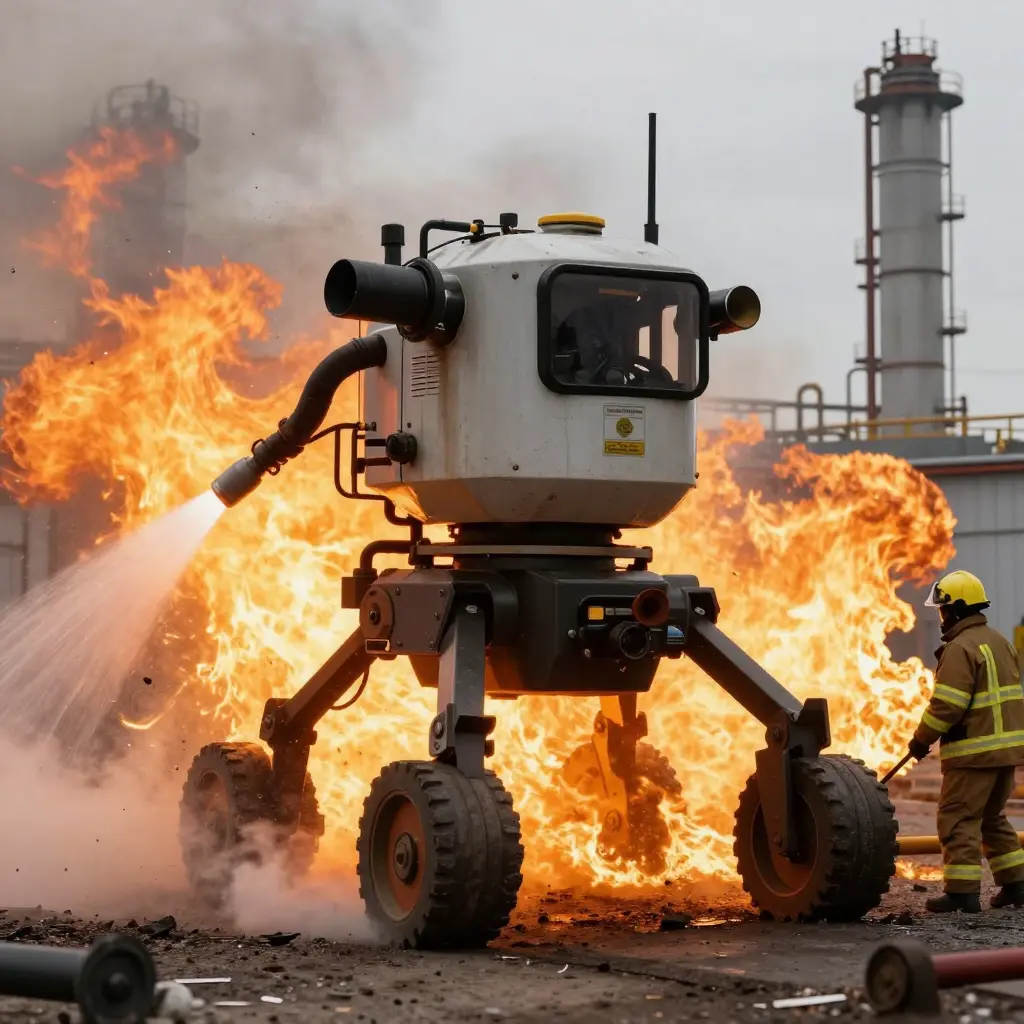
Two things limit an industrial firefighting robot inside a tank farm bund: radiant heat and the debris underfoot. Pump capacity, nozzle reach, travel speed and chassis class describe the machine on a clean, cool test pad. They say nothing about what it manages where a tank shell is radiating at high flux and the ground is already covered with failed insulation, shell plate and burst hose. Heat and debris attack different subsystems, and they usually do it at the same time.
Radiant heat reaches the machine before flame does. It drives thermal drift in cameras and infrared imagers, softening the picture the operator depends on for situational awareness. It cooks seals, cable jackets and hydraulic oil, so pump gland seals and valve seats begin to weep and the drive system loses efficiency. Nozzle actuators and pattern controls are often the first components to respond sluggishly, because they sit forward of whatever shielding the chassis carries.
Debris works on mobility and delivery. Track and wheel assemblies pack with grit, shredded cladding and set foam, which adds rolling resistance and makes steer inputs hang. Intake strainers load up and supply pressure drops. A stream that deflects off fallen structure loses its pattern. Sensor windows foul within minutes, so the operator is effectively driving blind.
Published ratings are a poor basis for procurement on their own. A unit has to be specified against the heat flux and debris field it will actually meet, then deployed inside those limits. Below: the heat limits first, then debris, then how to specify and deploy around both. Buyers still building the wider business case can start with the fireground tasks that actually justify a firefighting robot.
At a tank farm fire a robot seldom fails all at once. It reaches hard physical limits one mechanism at a time, and knowing where those limits sit is the difference between a workable deployment plan and an expensive recovery job.
- Radiant heat flux on exposed surfaces. Steel skins, seals, cable jackets and hydraulic lines take on energy faster than they can shed it, so surface temperature climbs until gaskets soften and fluid lines fail. That is why robot standoff distance is set from a measured heat flux rather than from how close the plume looks.
- Thermal derating of cameras, imagers and onboard electronics. Sensor housings heat-soak well before the chassis does, and image processors throttle output as internal temperature rises. The operator loses a usable picture at the moment the fire is most readable, which ends remote control while the machine is still running.
- Hose and umbilical exposure. Supply lines lying on hot ground or across burning product degrade from the outside in. One burst or coupling failure ends suppression, and once flow drops the machine has no protection of its own and has to withdraw.
- Embers and debris in the intake and cooling paths. Airborne ash and shredded insulation pack radiator cores and intake screens, cutting airflow until coolant and hydraulic temperatures reach alarm range. Cleaning intervals, not fuel, often set the working cycle.
- Debris under the running gear. Collapsed cladding, drum fragments and solidified product wedge into tracks, wheels or outriggers, stalling mobility or keeping stabilisers from deploying. A machine that cannot reposition is limited to a fixed arc of coverage.
- Blocked nozzle and distorted pattern. Ash, tank scale and partly burned product collect on the orifice and vanes, so the stream narrows or breaks up. Throw and foam blanket quality fall away and the fire gets a gap to re-establish.
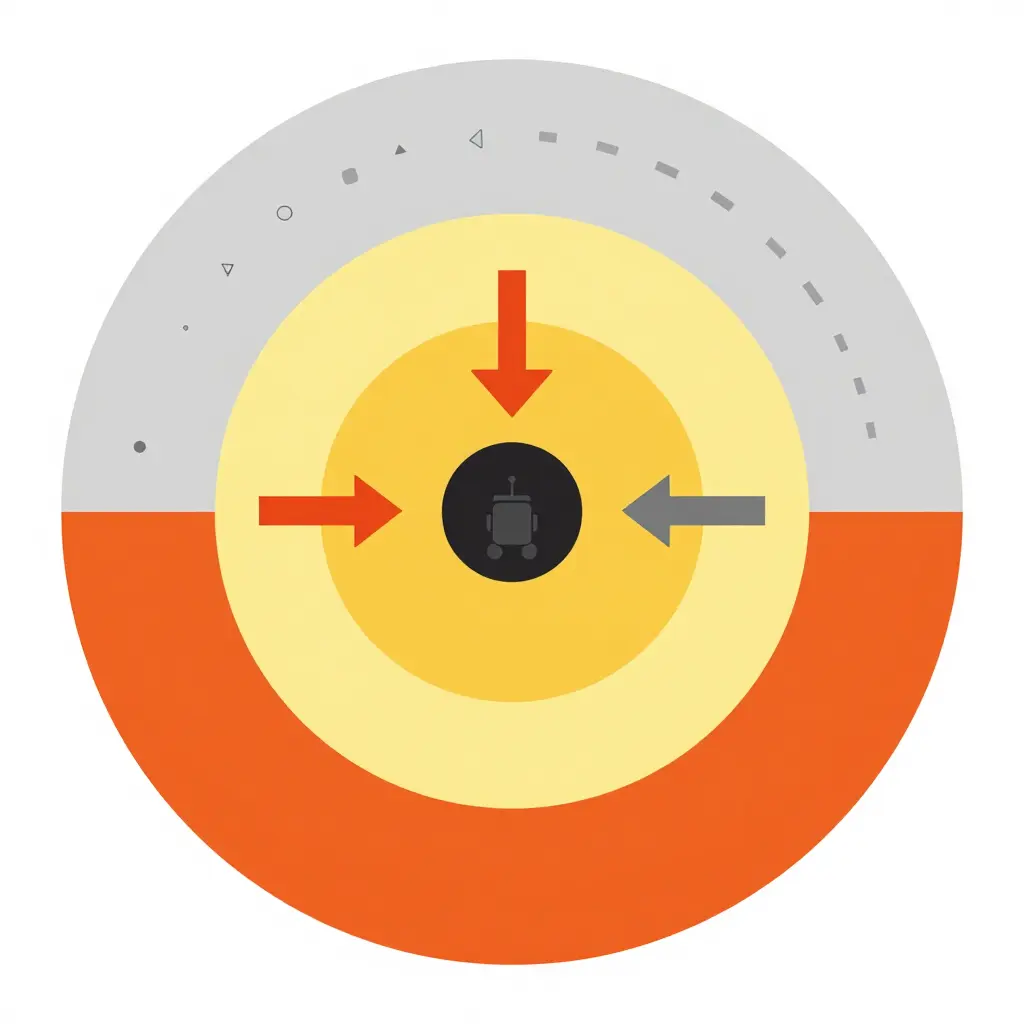
Place this schematic immediately after the bulleted list. Read it from the centre out. In the inner band, radiant load alone will cook sensors, hoses and tyres. The middle band is where a robot can still work, provided someone is watching it. Beyond that, falling debris and embers, not temperature, decide whether it holds its line. The two arrows carry the argument: heat pushes the machine back from the tank, debris pushes it off the access routes it needs. Where the two limits leave a strip of ground open, the machine can work, and that strip moves as the fire changes.
At a tank farm fire, heat usually sets the stopping point long before anything structural gives way. Radiant load on the chassis rises steeply as the unit closes on the tank line. For a flame front small relative to the gap, flux falls off roughly with the square of the distance, so halving the gap can put four times the energy on an exposed surface. The approximation weakens close in, where a burning tank wall is a large source and the falloff is gentler, but the direction holds. A firefighting robot that runs comfortably at 40 m may be at its practical limit at 20 m, and past it at 10 m.
Sensors and electronics go first
The steel frame and the boom will still be intact long after the machine has stopped being useful. What fails is the equipment that has to sense and decide: thermal cameras, IR detectors, encoders, motor drives, junction boxes, cable glands and sealants. Sensor housings heat-soak faster than heavy plate and hold tighter tolerances. Once a thermal camera drifts or an encoder drops out, the machine is blind or uncommanded with nothing melted.
A water film and a spray curtain absorb part of the incoming flux, and shield plates break the direct line of sight to the flame front. Both are on a clock. Water supply and spray coverage limit the duration, and plates conduct and re-radiate once soaked.
Hose and umbilical runs carry the heat exposure back toward the operator. The bundle trailing behind passes through the same hot zone as the machine, and the section closest to the unit takes the highest flux; a failed run costs the machine its supply or its control link. Run length also sets how far back the operator can stand, so the umbilical layout defines the crew’s real exposure distance.
A maximum ambient temperature rating is not a radiant flux rating. Ambient describes air temperature around the machine, typically measured in still air. Radiant flux is a separate, directional load, measured in kW per square metre on a surface facing the fire, and it can be severe while air temperature stays modest. Ask for irradiance-versus-time data and sensor derating curves, not a single ambient figure. On whether the machine belongs on the fireground at all, see when a robot deployment is justified; on how position changes delivered stream performance, see stream placement and turret reach.
Configuration decides as much as rating. The same machine works closer behind a shield or a curtain than it does in the open, and the hose run sets how far back the pump can sit.
| Deployment Configuration | Practical Heat Exposure Limit | Debris Tolerance | Recommended Use at a Tank Farm Fire |
|---|---|---|---|
| Remotely operated tracked robot with umbilical water supply | Moderate; lower than a fixed monitor, higher than a self-contained unit | Tracks cope with small rubble; the umbilical hose is the weaker point | Sustained shell cooling from mid-range where a stable water supply exists |
| Self-contained tracked robot with onboard monitor | Lower; onboard electronics and battery pack warm faster | Moderate at best; intakes and sensors stay exposed | Short-duration approach and quick knockdown where crews cannot stand |
| Rail or boom-mounted fixed monitor robot | Higher; drive gear sits away from the fire | Low; rails and booms are easily fouled by debris | Fixed deluge or monitor coverage of a specific tank or bund |
| Robot deployed behind a portable shield or water curtain | Raised compared with an unshielded unit of the same class | Moderate; shielding deflects rather than removes debris | Closer positioning with cooling pauses between passes |
| Manned firefighting vehicle held at extended standoff | High for the vehicle itself, though sustained radiant load still matters | Low; tyres, intakes and glazing are vulnerable | Command position, foam supply and monitor streams from a distance |
Figures above are indicative ranges only and should be validated against site-specific fire scenario assessments.
The Debris Boundary: Where a Firefighting Robot Stops After the Heat Is Beaten

Standoff distance and shielding usually answer the heat question first: the machine holds its ground, keeps the monitor trained, and the fire stops cooking it. Debris is the limit that shows up afterwards, once the fire is under control, and it tends to show up quietly.
Embers Clogging the Air and Cooling Paths
Fine ember carry lodges in air intakes, cooling passages and radiator fins, where it mats into an insulating layer instead of burning. Engine and hydraulic temperatures climb while the fire in front of the machine still looks controlled. A firefighting robot that ran cool an hour earlier can derate on nothing more than a fouled intake.
Ash and Residue Distorting the Spray
Ash, soot and unburned product residue settle into nozzle orifices and monitor passages, and the pattern bends out of shape before the flow rate visibly drops. A jet that should be a flat, penetrating fan becomes a ragged cone landing short of the tank shell. The same residue dries into flakes that break loose at the wrong moment, which is why dried foam flakes choke the first shot on many reel lines.
Rubble, Foam Crust and Blocked Routes
Structural fragments, torn cladding, collapsed pipework and set foam obstruct running gear and access routes across the bund. Tracks ride up on crusted foam and lose traction, and a machine that cannot reposition cannot re-aim. Residue behaviour on the ground is worth reading alongside this look at wind-driven runoff from foam blankets.
Cables, Umbilicals and the Retreat Problem
Tethers, power cables and cooling lines cross debris cleanly on the way in, when the path is fresh and the machine is moving deliberately. On the way out, the same debris snags, kinks and abrades insulation against hot edges. One chafed power core can end an operation with no flame involvement at all.
Why the Failure Arrives Late
Debris damage often disables a robot after standoff has already solved the heat problem, so the machine looks beaten by a fire it was winning. At a tank farm, that makes debris the boundary to plan for rather than something to sort out on the day.
Heat Load vs Debris Obstruction: Charting the Hardest Working Zone
Debris and heat rarely matter in isolation. One zone is choked with torn insulation, cable tray and drum remnants but stays comparatively cool; another is blistering and swept clean enough to roll through. What breaks a firefighting robot is the zone where both curves climb together. The chart plots a 0-100 relative index across four approach bands, from the outer perimeter to the tank line.
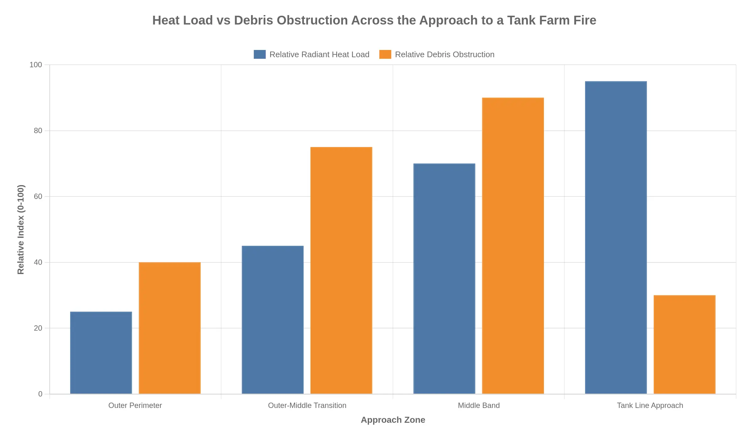
Reading the paired bars:
- Outer perimeter: heat 25, debris 40. A staging area, not a stress test.
- Outer-middle transition: heat 45, debris 75. First real resistance.
- Middle band: heat 70, debris 90. Neither number is low, and sensors, wheels and cooling all fight for margin at once.
- Tank line approach: heat 95, debris 30, because blast and fire have already moved or consumed much of the loose material.
The middle band does the hardest work, and it is the band a specification should be written against, not a showroom demo. See how to specify a firefighting robot for real fireground tasks.
Values are a relative index for comparison only, not site-specific heat flux measurements.
Planning Around Heat and Debris Instead of Pretending They Are Not There
Most tank farm incidents do not fail because someone bought the wrong robot. They fail because the specification assumed a clean, cool, unobstructed fireground that never existed. The fix is to build the limits into the purchase, the site layout and the written procedure before the alarm sounds.
Set a standoff distance you can actually hold
Decide the robot standoff distance from the tank line as a hard number, then buy the monitor to match it rather than working the other way round. A useful starting point is the distance at which radiant heat on the exposed side stays survivable for your expected run time, measured from the tank shell and not from the bund wall gate. Then confirm reach and pattern: a straight stream that reaches the shell but cannot wet the roof, or a fog pattern that builds a steam curtain nobody planned for, is the wrong monitor. Walk the route with a tape and a rangefinder at commissioning, and record the number.
Specify cooling protection, thermal shielding and sensor redundancy
A single headline temperature rating tells you almost nothing. Ask what happens to the industrial firefighting robot at 30 percent above that rating, and for how long. Specify water or air cooling for the chassis and running gear, reflective or ablative shielding around the control box and battery bay, and redundant temperature and camera sensing so one dead thermocouple cannot blind the operator. Insist on a documented derate curve rather than a marketing figure.
Treat debris as a design input
Tank farm firegrounds carry foam crust, ash, gravel, torn insulation and hose. Require intake screening that clears without tools, running gear sealed against foam concentrate and dirty water, and hose or cable routing that drags over a kerb without snagging. Then test it: run the machine through a debris bed before you sign.
Write the deployment doctrine down
Put three things on paper: the approach route and its inspection points, the retreat triggers (heat threshold, loss of vision, loss of telemetry, wind shift), and the post-run inspection interval for tyres, seals, intakes and cooling. Retreat on a trigger takes the argument out of the moment. Station and apparatus planning follow the same logic, since where the machine sits determines how fast it can reach a standoff line. See this guidance on planning bay depth for industrial fire stations and, for the air quality side of the same building, why diesel soot settles in apparatus bays.
What the robot can and cannot be relied on to do
Be clear with your board and your insurers. A firefighting robot can put water or foam on a tank shell, cool exposures, hold a line your crews should not hold, and keep working in smoke that would stop a person. It cannot extinguish a full surface tank fire on its own, cannot rescue anyone, cannot replace foam supply and water logistics, and cannot survive a debris-driven failure of its running gear or cooling. Buy it as a sustained, unmanned cooling and containment tool, and plan the rest of the response as though it might be out of service at any moment.
FAQ: Firefighting Robot Limits at Tank Farm Fires
How close can a firefighting robot operate to a burning storage tank?
Distance comes from the unit’s radiant heat tolerance and the cooling applied to it, not from a rule of thumb. Most tracked units with thermal shielding and a spray curtain can hold ground roughly 30 to 50 metres from a fully involved tank, but the manufacturer’s radiant flux rating is the figure that governs positioning. Past that envelope, chassis, tyres, hoses and sensors begin to fail in sequence.
Is heat or debris the more common limiting factor?
Heat is predictable and debris is not. Radiant flux can be estimated from tank diameter, flame height and wind, so a working position can be planned around it. Debris fields, whether shell fragments, collapsed roof sections, set foam or drum remnants, arrive without warning, and they end deployments more often than temperature alone. Heat sets the operating window; debris decides whether the unit gets out.
Can a firefighting robot replace a manned response at a tank farm fire?
No. A robot holds ground in the hot zone. It does not replace a command structure, pump operators, foam supply or entry teams. Crews still establish water supply, direct the monitor and make the tactical calls, and the unit works best as an extension of the manned response that keeps people out of the most exposed position. Which fireground tasks actually justify a firefighting robot is worth reading before you write one into an emergency plan.
How can debris damage be reduced during operation?
Keep the unit far enough back that thrown material has already landed, knock embers down with spray curtains, and route it on graded hardstanding rather than gravel or rubble. Guards over intakes, cable runs and cameras help, but recovery planning matters more, because in debris-driven failures it is track and tyre damage that immobilises most units, not electronics. Washing foam residue off the chassis after each deployment also limits corrosion.
What information is needed to select a firefighting robot for a tank farm site?
You need tank diameters and spacing, bund wall heights, available water supply and flow, and the maximum credible fire scenario for the site. Check the robot’s radiant heat rating, monitor flow and throw, run time, gradient capability and remote operating range against those figures. Site access routes, ground surfaces and the local brigade’s tactical plan complete the brief.