Apparatus bay floor loading and the late-cracking problem
Apparatus bay floor loading means the loads a station slab carries while fire apparatus sits parked, moves in and out, and is lifted for service: vertical wheel loads, the dynamic forces of turning and braking, concentrated jack and outrigger reactions, and the effect of all of them on concrete that may never have been tested against them. Slabs are designed and poured as structurally sound, and at handover they usually are. The trouble starts years later, when a fully loaded apparatus parks on the same footprint every day and the surface begins to crack.
Cracking is rarely one failure. It comes from a load path that concentrates stress where the design expected it to spread, from assumptions that treat the bay slab as a parking surface rather than a working floor, and from construction and maintenance decisions taken years before the first vehicle rolled in. Those assumptions show up early in bay depth and sizing decisions, long before anyone measures slab performance. Once a crack is open, water, chlorides and de-icing salt reach the reinforcement, and the repair stops being cosmetic.
The rest of the article takes those in turn: how load travels from tyre and jack into the slab, which design assumptions carry the most risk, where construction and maintenance widen the gap, and what a station owner can write into the specification at design, handover and inspection.
Design load versus actual load in an apparatus bay slab
Design offices rarely see the numbers that turn up on site. Once the bay is built, nobody re-checks the floor against the vehicle that parks on it, and slab decisions are frozen at the same time as bay depth and layout decisions. The table sets what a slab is normally designed for against what a loaded crash tender actually puts into it.
| Load case | Typical design assumption | Real-world value on a loaded apparatus | Effect on the slab |
|---|---|---|---|
| Single wheel patch, loaded drive axle | Uniform patch, 300 x 300 mm | 60–80 kN under one tyre footprint | Local punching, radial cracking |
| Tandem or triple axle group | Axles assessed individually, well spaced | 300–400 kN across three closely spaced axles | Overlapping stress bulbs, deeper cracking |
| Outrigger or jack point during stabilisation | Load spread at 45 degrees through pad | 100–150 kN on a small steel pad, 200–400 kN on an aerial outrigger | Punching shear at pad corners |
| Tyre contact pressure vs assumed area load | Uniform 10 kPa spread across the bay | 700–900 kPa at the contact patch | Surface abrasion, high local stress |
| Dynamic impact from braking or turning | Static load, factor of 1.0 | 1.3 to 1.5 times static while braking | Fatigue at joints, edges, saw cuts |
| Loaded trailer or turret maintenance stand | Minor point load, often ignored | 40–60 kN on four small feet | Star cracking around base plates |
The rows point at the same thing: a distributed area load is a convenient simplification. What reaches the concrete is a set of concentrated point loads, and the gap between design and service is why cracks appear years after handover instead of at commissioning.
How apparatus loads reach the slab
Everything a loaded apparatus weighs enters the building through the small rubber patches where its tyres meet the floor. Force that weight through patches that size and the pressure at the surface lands close to the tyre inflation pressure: 700–900 kPa, against the 10 kPa area load the design assumed.
Load also rarely arrives one wheel at a time. Dual tyres share an axle line, tandem and triple groups stack two or three of those lines close together, and a stabiliser jack drops its whole force onto a pad roughly 300 mm square. The same total load ends up carried by fewer, smaller patches.
Whether the slab absorbs all this or fails comes down to four things working together: thickness, reinforcement, joint layout and subbase support. A thick, well reinforced slab over a stiff, well compacted subbase spreads the force outward at a gentle angle, so pressure fades before it reaches anything weak. A thin slab, light reinforcement, a joint sitting where the tyres park, or a subbase that settles all let the same force punch through instead of spreading. Poor subbase support is the quiet one, because a slab cannot bridge a void it was never designed for. At design stage, review bay depth and slab design before the pour rather than after the cracks.
What decides whether the slab lasts its first decade is where the load concentrates, not the gross vehicle weight on the door plate.
The load path is not a straight push-down
Load enters the slab through a tyre contact patch no bigger than a dinner plate. Below that patch the force does not sink straight down; it spreads outward, at something like 45 degrees if the design assumption holds. That cone is what the diagram draws in cross-section: contact patch, spreading front, reinforcement layer, joint line and compacted subbase.

Read it from the top down. Where the cone is still narrow, punching shear and local crushing govern. Where it meets the reinforcement layer, the steel starts carrying tension the concrete cannot. Past the joint line, load transfer depends on aggregate interlock and dowel action, which is why joints and edges are where distress appears first. The cone is a convention, not a description: in a thin slab over a stiff subbase the real spread is steeper, and the concrete within a few hundred millimetres of the patch works harder than the idealisation suggests. If you are still narrowing down bay dimensions, our industrial fire station bay depth sizing guide covers the geometry side of the same problem.
Walk any bay after a busy shift and most of this is visible before it reaches a repair budget.
- Hairline cracks fanning out from the wheel paths: point loads punching past what the slab was designed for.
- Cracks tracking along a joint line: curling, or load transfer between pours already lost.
- Spalled, crumbling edges at free ends: subbase exposed, edge load and impact together.
- A dull, hollow note under a dropped weight: delamination, or a void under the surface.
- Water standing after wash-down: settlement has flattened the fall the slab was poured to.
- A step at the door threshold: the slab is moving independently of the apron outside.
- Rust staining or exposed bar near joints: cover gone, chlorides in behind it.
- Cracks widening week over week under the same parking pattern: fatigue, not one-off shrinkage.
Why slabs crack years after handover
Concrete does not stop changing at handover. Drying shrinkage carries on for a year or two, sometimes longer, as residual moisture leaves the slab, and restraint from grade beams and trench drains turns that contraction into tension at the surface. Flat, sound slabs open hairline cracks this way, slowly enough that nobody notices the first stage.
The support underneath changes too. Fines migrate into voids under repeated wheel passes and soft spots consolidate, so the pour ends up spanning a gap it was never designed to span. How much that matters depends on geometry: a short span between joints bridges a small void, while a long bay over a drain line bends, and a crack that bends opens and closes with every axle. This guide to bay geometry and slab span explains why.
Each wheel roll and each jack placement adds a load cycle. Cycles work the joints and their sealant open a little further, water reaches the subbase, and the subbase loses the stiffness that was spreading the load in the first place. Standing water left by poor drainage does the same work from the other side, softening the floor and corroding the chassis. None of it is dramatic, which is why it takes years to become visible.
Crack width progression in a loaded apparatus bay slab
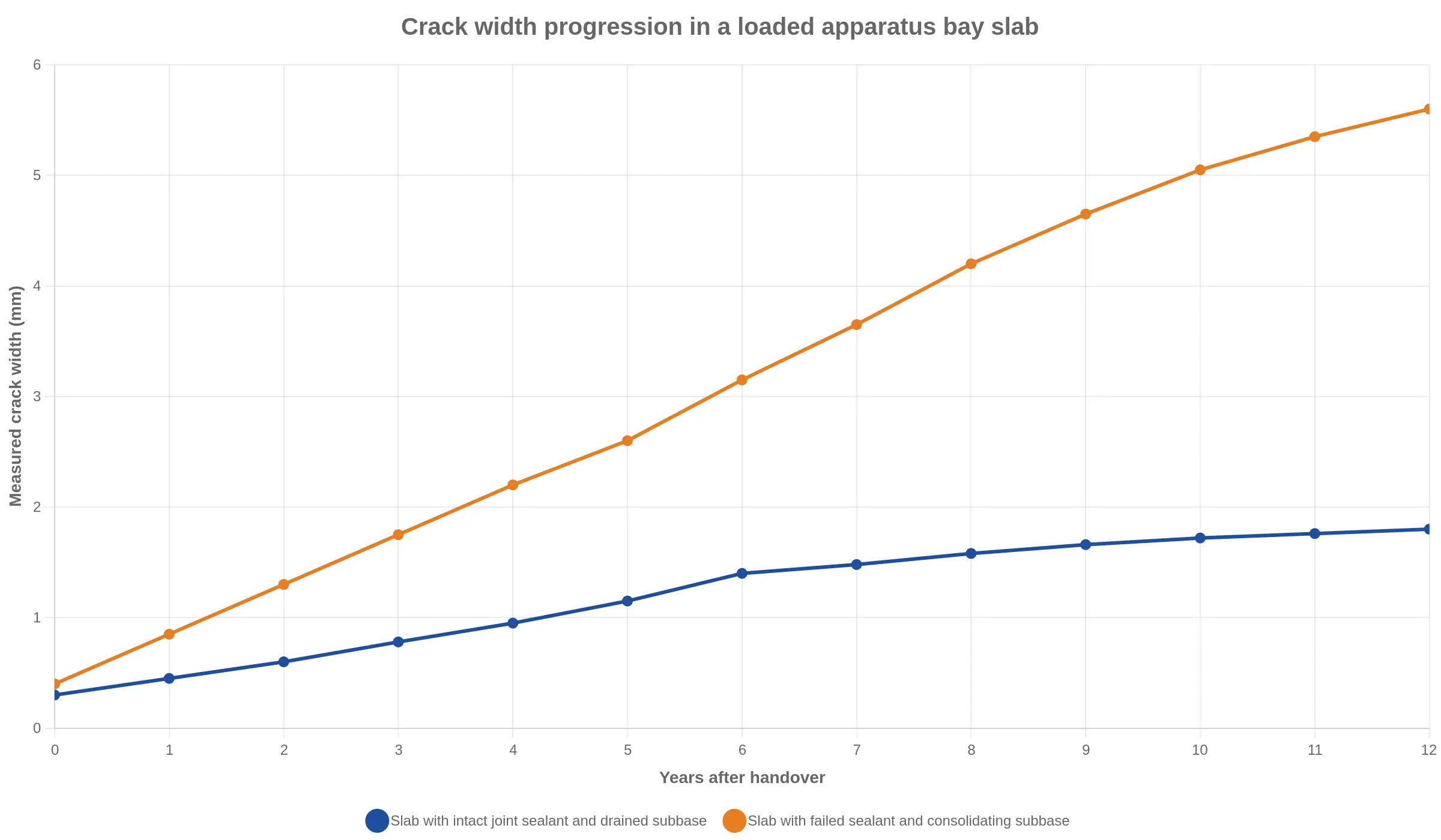
Both slabs leave handover at much the same point, around 0.3–0.4 mm. After that they diverge. The blue line rises slowly and flattens just under 2 mm; the orange line keeps climbing, passes 5 mm by year ten and never settles. What separates them is not the original design: it is the joint sealant and the drainage, which decide how quickly a hairline becomes a structural crack. At planning stage, review your bay depth and slab sizing assumptions so those details are designed in from day one instead of patched in later.
Specification and remediation guidance for station owners
Most bay floor problems are decided before the first pour, and the biggest lever a station owner holds is the wording of the tender documents. A blanket area load in kilopascals is not a substitute for real data. Ask the vehicle manufacturer or your fleet engineer for actual wheel loads and outrigger or jack loads per axle, at rest and under braking, and write those figures into the specification so the structural engineer can check point loads and punching shear properly. Ask in parallel for a geotechnical assessment of the subbase — bearing capacity, settlement potential, moisture sensitivity and verified compaction, not only a plate load test taken on the day of inspection. Apparatus bay slab design that ignores subgrade variability is how you end up with slow slab cracking that only appears years after handover, once the ground beneath has had time to move.
Joint sealant and drainage details deserve the same specificity, because most cracks start at a joint, penetration or drain rather than in the middle of a panel. Spell out joint layout and spacing, sealant type and the movement it must accommodate, dowel and tie-bar arrangement, and the fall to drainage with anchorage for trench gratings so they cannot work loose under wheel impact. The load on the slab is never a single figure either: a crash tender running with a full water tank applies a different weight and stress distribution than the same vehicle at part load, and liquid movement under braking shifts that load forward. It is worth knowing how the tank baffles behave before assuming one design number covers every operational state.
Inspection belongs in the specification too, not in the afterthoughts. Mark reference stations on the slab, record baseline crack widths in the handover file, and set explicit action thresholds — monitor anything above a hairline, commission a structural review beyond a defined width. Set those thresholds at door openings, apron transitions and around floor-mounted equipment. Interfaces are where distress concentrates: exhaust extraction systems, turntable plates, hose reels and drains each create a stress point and a water path, so list them as named inspection items and revisit them on a fixed cycle rather than waiting for a failure to announce itself.
Frequently asked questions: apparatus bay floor loading and slab cracking
Is a cracking apparatus bay slab an immediate safety issue, or only over time?
Not usually immediate, but never purely cosmetic. A crack that stays tight and dry is reporting stress; one that widens, offsets or takes water is already undermining the slab. Treat displacement or spalling as urgent whatever the crack width reads.
How long after handover does slab cracking typically become visible?
Most first cracking shows up within 12 to 36 months, often after a seasonal wet–dry cycle or the first sustained heavy loading. Cracking that first appears at year five is late: shrinkage and settlement stress have usually been accumulating since the pour.
Do surface coatings or overlays solve the problem?
Rarely on their own. A coating hides the hairline and changes nothing below it; an overlay adds dead load without correcting the subgrade or the thickness deficiency. While the structural cause remains, the slab keeps cracking and the overlay delaminates.
How do outrigger or jack loads compare with parked wheel loads?
A single pad carries far more than one wheel. A tender’s stabiliser jack can put 100 to 150 kN on a small steel pad; an aerial’s outrigger, 200 to 400 kN, or 20 to 40 tonnes. A loaded wheel puts 60 to 80 kN through its contact patch. The wheel spreads that over the tyre footprint; the jack does not.
What information should a station owner request from a slab designer or contractor?
Request design wheel and outrigger loads, slab thickness, concrete strength, reinforcement details, joint layout, subgrade bearing capacity, and drainage. Also ask for the load calculations behind the apparatus bay slab and for as-built drawings; our industrial fire station bay sizing guide covers the dimensions those answers have to fit.