Why Diesel Soot Settles Before Extraction Clears the Bay
An idling diesel releases soot in a burst, and extraction needs a moment to catch up. Exhaust leaves the tailpipe with enough momentum to carry the plume a short distance, then the heaviest particles begin to drop, often within seconds. At the hose connection the fan is still coming up to flow, and anything outside the capture cone is not collected.
That gap between timing and geometry is why ledges, apparatus tops and floor edges collect diesel soot in a bay where the system is installed, switched on and working. The airflow is real. It reaches the particles after they have already left the moving air.
Hose routing and bay depth have to be planned around that lag; a larger blower does not remove it. Whether the capture cone stays over the plume long enough is settled at the drawing stage, when drop points and apparatus positions are fixed. This guide to bay depth sizing covers the layout side of that calculation.
Why Soot Leaves the Extraction Path
Diesel particulate is a size spectrum, not one substance, and size decides how long each fraction stays airborne. A particle falls when gravity beats drag. Capture velocity is the air speed that has to beat gravity first.
1. Particle size and settling velocity
For fine particles in the Stokes regime, settling velocity rises with the square of diameter, so a particle twice as wide falls four times as fast. The visible black agglomerates are large enough to leave that regime; they settle faster still, though their velocity no longer scales with the square of diameter. The fine and nanoparticle fraction falls far more slowly and can stay suspended long enough to cross the bay.
2. Capture velocity versus transport velocity
Capture velocity is measured at the nozzle face: the air speed just ahead of the inlet, chosen to pull the plume in against cross-draughts and vehicle movement. Transport velocity inside the hose is a separate figure, calculated only to keep entrained material from settling in the duct. Neither one cleans the room. A particle released outside the capture cone is already past the point where the design works.
3. Buoyancy and thermal rise
Hot exhaust leaves the tailpipe buoyant and climbs, drawing room air in behind it. As it cools it loses lift, and once it stops rising it drifts and falls instead of travelling sideways to the extraction point. That is why nozzle position and start timing matter more than raw airflow. Both depend on layout, as this bay geometry and extraction layout guide sets out.
The three linked factors
- Size: coarse soot drops in seconds; fine soot stays suspended and travels.
- Velocity: capture velocity holds a plume at source; transport velocity only keeps entrained material moving.
- Buoyancy: hot exhaust lifts, cools, stalls, then falls away from the nozzle.
Those three explain a bay that shows visible soot on floors and horizontal surfaces while the extraction system runs exactly as designed.
Extraction Approaches Compared
| Extraction approach | Where soot is captured | Capture point relative to source | Particle fraction kept in the bay air | Bay layouts it suits |
|---|---|---|---|---|
| Tailpipe hose connected at source | Inside the hose at the tailpipe outlet | At the source, before the plume forms | Minimal; only what slips past the coupling | Drive-through and single-position bays with fixed apparatus spots |
| Overhead rail or drop-hose reel at the apparatus position | At the stack or hood above the cab | Above the source, still inside the plume | Small; residual from uncoupled idling | Long bays, tandem parking, multi-position layouts |
| General dilution ventilation through the bay | Diluted and carried through the whole volume | Downstream, after the plume spreads | High; whole-bay concentration rises | Large, high-ceiling bays with generous air changes |
| Portable fan or temporary negative pressure | Pushed toward an exhaust opening | Downstream, after plume dispersal | High along the fan path, uneven elsewhere | Bays without a fixed system, or short-term backup |
| No extraction | Deposits on floor, apparatus and surfaces | None; plume disperses freely | Very high; full bay loading | None; not a control strategy |
Only source capture acts on soot before it leaves the plume. Dilution lowers the concentration in the bay air, but the soot is still in the room until it is exhausted, and much of it settles first. If capture points have to work around apparatus positions that are already fixed, settle the layout before ordering hoods. Bay depth and layout sizing covers the options.
Verification Checklist: Confirming Capture at the Tailpipe Connection
- Verify the nozzle-to-tailpipe seal sits flush, with no visible gaps or loose slack.
- Measure capture velocity at the nozzle face and log each reading against the baseline.
- Confirm the fan starts automatically within seconds of engine start, every time.
- Check hose length and routing against the parked position of the apparatus in each bay.
- Inspect fan blades and duct joints for leaks, cracks and heavy soot buildup.
- Record filter loading and discharge condition before the first engine run of the day.
- Run a documented smoke or particle-count check and log the results.

Figure 1. Relative soot concentration in the bay air after engine start, plotted against elapsed minutes for three extraction strategies. The source-capture curve peaks at engine start and falls steeply within the first five minutes. Dilution ventilation declines slowly and levels off well above zero. With no extraction the curve barely moves and the bay stays loaded with soot.
Caption: Concentration in the bay air is the outcome you measure; capture velocity at the source is the input you can control. Ventilation cannot fix a plume that was never captured at the pipe.
Before re-specifying hoods and hose drops, check the layout against the building itself. Apparatus bay depth sizing sets out the numbers.
Bay depth sets the distance between the exhaust stack and the drop point. Park a rig too far forward or too deep and the plume can enter a low-velocity pocket before it reaches the hood; those clearances are covered in this bay depth and apparatus clearances guide. Align the drop point with the actual exhaust location, not the nominal vehicle centerline.
Open bay doors bring cross-draughts that push the rising plume sideways, off the capture point. Supply and exhaust also have to stay in pressure balance: too much supply pressurizes the bay and drives soot-laden air out through the doors, while too much exhaust starves the drop point and pulls contaminated air in through gaps. Doors, fans and make-up air behave as one coupled system in a fire station bay.
Air turns over slowly above apparatus tops and behind parked vehicles. Soot that drifts into those pockets cools, loses buoyancy and settles before the system can clear it, which is why stagnant volumes need mapping when hoods are sized and inlets positioned.
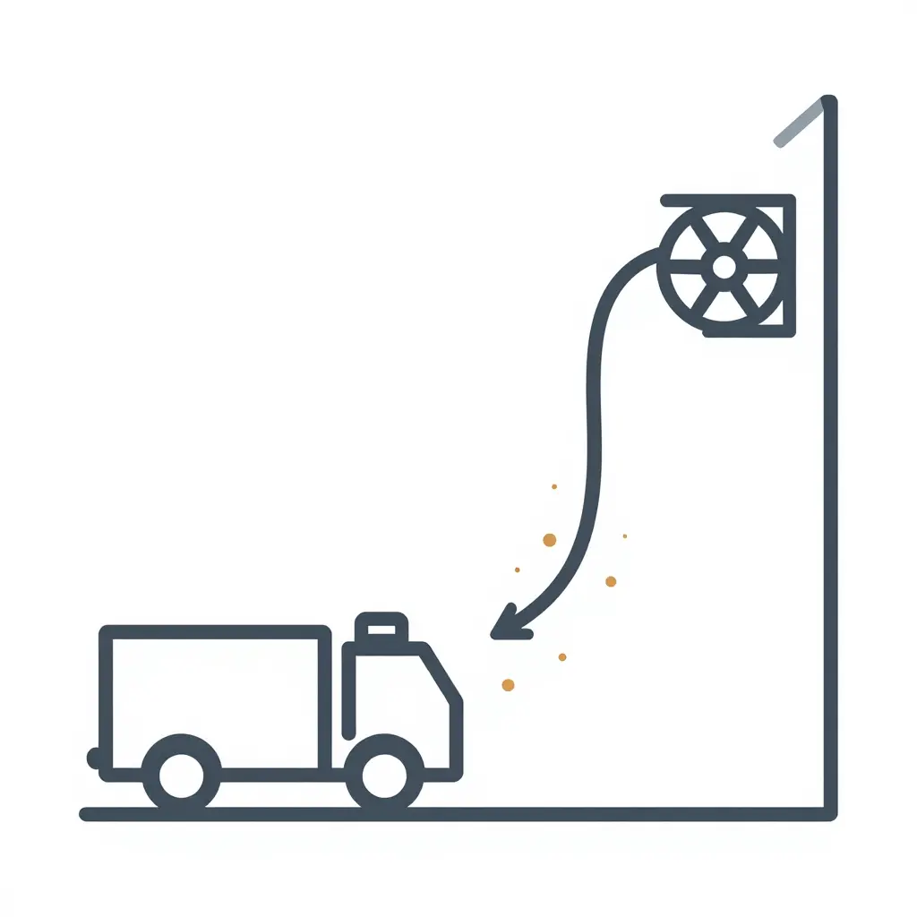
Reading the schematic
Supply air enters low at the open door and warmer air lifts out above it, but that loop does not sweep the whole floor. Above and behind the apparatus, the draught stalls and leaves still air in the shaded pocket. Soot drops out of suspension there before the extraction path ever reaches it.
Depth, door height and where the plume actually goes decide how large that pocket becomes. The sizing logic in this bay depth and equipment clearances guide applies just as directly to how cleanly the air in the bay turns over.
What Owners Should Specify and Keep Verified
Start with the numbers that cannot be changed later. Fan and hose size should follow the number of apparatus positions, the engine sizes and the duct run length, and automatic start has to be interlocked with engine start so capture begins before soot reaches the bay. Specify capture velocity measured at the nozzle rather than fan capacity alone, and state in the specification how it will be tested. Prolonged standby idling also raises soot output and changes how fast a bay loads up, so read this walkthrough of standby idling and DPF soot loading before fixing airflow margins. Then set a service and verification interval for hoses, ducts and discharge points, and keep the records current, so the system can be shown to work instead of assumed to.
On the specification sheet: fan and hose sizing per position and engine size; auto-start interlocked to engine start; nozzle capture velocity stated as a measured figure, not a fan rating; a fixed, verified service interval for hoses, ducts and discharge points.
FAQ: Soot Settling and Extraction Performance
Why does diesel soot settle even when apparatus bay exhaust extraction is running?
Because capture only works while the nozzle is connected and the fan is drawing. Soot released after shutdown, after a hose disconnect, or outside the capture zone has no directed airflow to carry it, so it falls onto floors, ledges and apparatus.
Can general ventilation replace source capture?
No. General ventilation dilutes and slowly exchanges bay air, so diesel soot spreads through the space before it is removed, and part of it settles on downstream surfaces as it goes. Source capture keeps capture velocity at the emission point, something ventilation working at a distance cannot achieve.
How quickly do downstream surfaces accumulate diesel soot after a system is installed?
With imperfect capture, a visible film often shows up within weeks on ledges, lift posts, hose reels and high steel. How fast depends on daily apparatus movements, idle time and how consistently the nozzle is actually attached.
Does a larger fan alone prevent settling?
No. A larger fan raises total airflow, but hood shape, duct length, leaks and open bay doors all bleed suction, so fan rating says little about velocity at the tailpipe. Capture depends on velocity at the source, which is why duct and bay depth planning matters as much as the fan.
How often should capture performance be re-verified?
At least annually, and again after any change to the duct, fan, hood or nozzle, or if visible diesel soot comes back to surfaces. In a busy apparatus bay, quarterly smoke or velocity checks are reasonable.