How the Nitrogen Expellant Circuit Works on an ARFF Crash Tender
Dry chemical powder does nothing on its own. On an ARFF crash tender, the push that moves it comes from stored nitrogen, and the gas follows a fixed path through six components. Knowing that order is the quickest way to trace a weak or failed discharge.

1. Nitrogen cylinder
A high-pressure cylinder holds the expellant gas: inert nitrogen, compressed and non-reactive, which pushes the agent out of the system. Nitrogen works here because it is dry and chemically lazy. It will not react with the powder or carry moisture into it.
2. Pressure regulator
The regulator drops full cylinder pressure to a stable working value. Its setpoint is the output pressure it holds, far below bottle pressure, so the tank and everything downstream of it are not over-pressurized.
3. Expellant manifold
The manifold is the distribution block that routes regulated nitrogen to one or more dry chemical agent tanks. It gives the system a single feed point and usually carries the gauge a technician reads during inspection.
4. Check valve
A check valve allows flow into the tank in one direction only, blocking powder or moisture from traveling back toward the regulator. The part is small, but it keeps the nitrogen circuit upstream of the tank clean.
5. Dry chemical agent tank headspace
The headspace is the void above the powder bed inside the tank. Nitrogen entering the tank builds headspace pressure, and that trapped gas pressure is what actually drives the agent out.
6. Discharge valve
Open the discharge valve and the nitrogen-charged powder leaves the tank, travels down the discharge line, and exits the nozzle at whatever rate the headspace can sustain.
From stored charge to powder flow
At rest, the cylinder holds the system’s entire energy reserve. Arm the system and regulated nitrogen moves through the manifold and check valve into the headspace, raising the pressure there.
That pressure works gas into the gaps between powder particles, aerating them until the powder flows instead of moving as a solid slug. When the discharge valve opens, the fluidized agent travels the discharge line and hits the fire.
The problem is that none of this is visible. A slow nitrogen bleed leaves no stain, trips no alarm, and changes nothing you can see on a parked truck. It looks exactly like a fully charged system until the moment someone needs it. The same logic drives undetected pressure drift on the ramp, where a silent deviation in a pressure-driven system stays hidden until the incident. Gauge checks and scheduled pressure verification are what catch it.
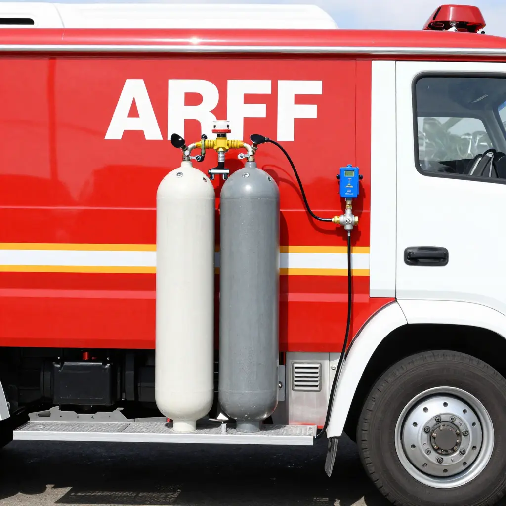
Figure: flat schematic of the nitrogen expellant circuit on an airport crash tender dry chemical system, showing the nitrogen cylinder, pressure regulator, expellant manifold, check valve, dry chemical agent tank with headspace, and discharge valve connected by flow lines and arrows.
Root Causes of Nitrogen Pressure Bleed-Down During Long Idle
A dry chemical system keeps its powder under constant nitrogen pressure so the agent discharges the instant an operator actuates it. During long idle periods that charge can ebb. The truck still looks mission-ready, but it may no longer be able to push powder through the hose line at full rate. Finding where the nitrogen is going is the first job in any maintenance program, and the likely causes fall into a few groups: gas migrating through materials, seals that have worn, and effects that are not leaks at all.

Seal Permeation and Microscopic Regulator Diaphragm Leaks
Every elastomeric seal and regulator diaphragm is slightly permeable to gas. Nitrogen molecules migrate through the diaphragm material and past O-ring faces, producing a small, steady decline that is entirely normal. This seal permeation is not a failure. A diaphragm that has aged or swollen from chemical exposure is a different matter: it can allow regulator creep, where the downstream set pressure drifts and the charge dissipates faster than baseline. The driver here is material degradation from heat cycles and time in service.
Permeation and Slow Leakage Through Flexible Expellant Hoses
The flexible hose between the cylinder and the tank gives gas a large surface to escape through. Nitrogen passes through the polymer wall at a steady rate, and over a year of inactivity the hose alone can account for a meaningful share of nitrogen charge decay. Age, UV exposure, and high ambient heat all speed that up. A hose already cracking at the coupling will leak far faster than wall permeation.
Check Valve Seat Contamination or Cracking
A contaminated or cracked check valve seat is a common cause of an unexplained dry chemical system leak. Powder residue carried back toward the valve during operation can lodge against the sealing face and keep it from closing gas-tight. Repeated cycling and pressure shock can also fatigue the seat until it micro-cracks and lets expellant gas bleed back toward the cylinder head. Because a dirty seat often leaks intermittently, it is easy to misdiagnose.
Cylinder Valve Packing Degradation
Packing seals the cylinder valve stem, and that packing dries, shrinks, and hardens over time. As it degrades, gas escapes past the stem threads, especially on systems that are rarely cycled. The packing never gets the exercise that keeps it pliable, which is why this failure shows up on trucks that sit.
Thermal Contraction of the Nitrogen Charge in Cold Hangars
Not every pressure drop means a leak. Nitrogen follows the gas laws, so a charge filled in a warm bay and parked overnight in an unheated hangar will read lower purely because it contracted. The effect reverses as the gas warms, which is why readings need correcting to a reference temperature. The same swings that distort pressure also affect stored agents, so temperature swings shorten agent shelf life is worth understanding before you call a cold-weather drop a leak.
Gradual Loss at Threaded and Flanged Fittings
Threaded NPT joints and flanged connections stay tight through preload and sealing compound. Torque relaxes over time, vibration loosens fasteners, and sealant ages, opening tiny leak paths that widen slowly. Any one of them is trivial; several weeping fittings together add up to a measurable decline.
Acceptable Permeation Versus an Unacceptable Leak Rate
A properly sealed system always loses some pressure to permeation, and that is fine. The rate is what matters. The table below separates normal behavior from a condition that needs repair.
| Indicator | Acceptable (permeation) | Unacceptable (leak) |
|---|---|---|
| Annual pressure loss | A few percent, stable month to month | Steady, accelerating decline |
| Behavior after recharge | Holds and plateaus | Continues dropping within days |
| Location of smell/soap test | No external bubbles | Bubbles at fittings, hoses, or stem |
| Reading over 12 months idle | Stays above the minimum service threshold | Falls below it well before the year ends |
A correctly sealed system should hold its charge well above the manufacturer’s minimum service pressure for at least twelve months of idle storage, with only minor variation once the reading is corrected for temperature. The chart below shows the difference between healthy permeation and a developing leak.
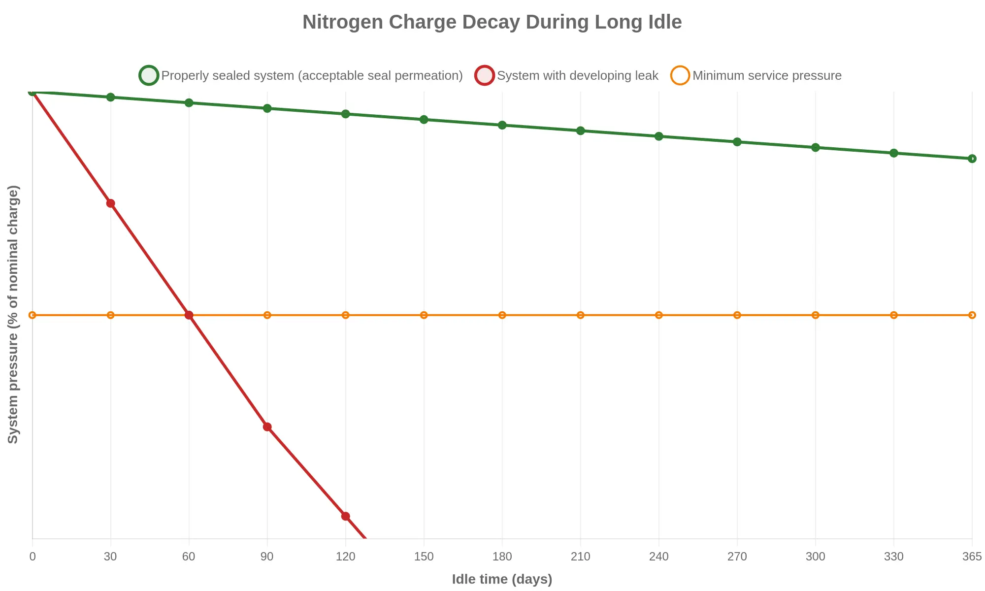
Drift that accelerates, pressure that holds only after repeated top-ups, or a soap-bubble indication at a fitting all point to a real leak rather than normal permeation. Log monthly readings and correct them to a reference temperature, and you can catch a failing check valve seat or hardened valve packing long before it grounds the truck.
The table below lists the most common leak points on this system, each paired with its field symptom, probable root cause, the fastest way to confirm it, and the corrective action. Keep it handy when a system bleeds down during a long idle.
| Component / Leak Point | Typical Symptom | Likely Root Cause | Inspection Method | Corrective Action |
|---|---|---|---|---|
| Nitrogen cylinder valve | Slow, steady pressure decay with the system isolated | Worn valve stem packing or hardened O-ring seal | Apply leak-detection fluid at stem and outlet; watch for bubbling | Replace stem seals or the valve; torque outlet fittings to spec |
| Pressure regulator diaphragm | Creeping downstream pressure; erratic gauge response | Aged or chemically swollen elastomeric diaphragm | Isolate regulator, hold constant inlet pressure, and monitor outlet drift | Install a new diaphragm kit; bench-test the regulator before refit |
| Expellant hose fittings | Localized pressure loss; frost or residue at a joint | Loose JIC/flare nut or cracked ferrule | Pressurize and coat fittings with soapy solution; observe bubbles | Re-torque to specification or replace the hose assembly |
| Check valve seat | Pressure back-bleeds into the supply line during idle | Contaminant lodged on the seat or a nicked sealing face | Isolate the valve and check for reverse flow with gauges on both sides | Clean or lap the seat; replace the check valve cartridge |
| Agent tank headspace | Gradual loss even when all valving is closed | Porous weld seam or degraded tank gasket venting gas | Perform a vessel leak test; inspect seams and gasket with leak fluid | Repair the weld or reseal the gasket per the manufacturer’s procedure |
| Threaded and flanged joints | Intermittent decay that varies with ambient temperature | Insufficient torque, dry threads, or relaxed flange bolts | Systematic leak survey with detection fluid or an ultrasonic listener | Re-torque to spec with the correct sealant; replace gaskets as needed |
| Pressure gauge | Gauge reads low or will not hold after charging | Leaking Bourdon tube or failed gauge stem seal | Isolate the gauge and check for decay against a calibrated reference | Replace the gauge; verify calibration before reinstalling |
On idle ARFF dry chemical systems, three areas account for most chronic pressure loss: the nitrogen cylinder valve, the pressure regulator diaphragm, and threaded and flanged joints. Check those first and most bleed-down complaints can be resolved without invasive teardown.
Common Warning Signs of Nitrogen Pressure Bleed-Down
Watch for these early indicators of nitrogen pressure loss before they compromise discharge performance on the ramp.
- Setpoint drift after idle: the gauge reads below the regulator setpoint after a long idle, even though the tank was not discharged and nothing was recently serviced.
- Weak functional discharge: the powder comes out sluggish or incomplete during a functional test, with reduced throw distance and a thin plume at the nozzle.
- Frost or oil at fittings: frost or oily residue shows up near regulator fittings, valve stems, and nitrogen charge ports, which points to a slow, sustained leak.
- A failing pressure-hold test: pressure declines gradually and the system cannot hold its setpoint across a 30-minute monitoring window.
- A hiss or bubbles: a faint hiss, or soap bubbles that keep growing, at threaded joints, hose couplings, and Schrader valves during leak detection.
- Frequent recharges: nitrogen runs out between scheduled services, so the truck needs top-ups sooner than the manufacturer’s baseline.
Read these symptoms as a connected chain of evidence, not as isolated faults. A single low gauge reading may mean nothing more than a cold morning. Pair it with frost at a fitting and a slow pressure-hold decline and the pattern points to a real leak path rather than a gauge or regulator error. Note when the drift started alongside idle duration, recent service work, and where the physical indicators appear, and a maintainer can tell a genuine nitrogen loss from a false positive. Record every observation and retest under the same conditions; a slow leak is much easier to catch on paper than to discover when a call demands full discharge pressure.
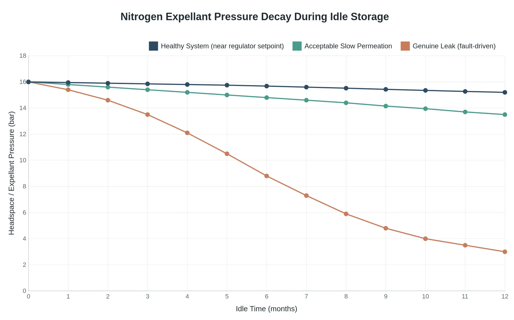
Diagnostic takeaway: a healthy system holds close to its regulator setpoint with only minor seasonal drift; an acceptable permeation trend declines in a smooth, predictable slope; a real leak falls away steeply and diverges from both baselines, which means it needs leak testing immediately.
Step-by-Step Troubleshooting Procedure
Treat every reading as evidence before you touch a fitting. The goal is not to find a leak fast; it is to prove which component holds pressure and which one bleeds it away while the truck sits idle.
Work the sequence in order. Skip a hold step to get to a suspected culprit and you are the technician who replaces a good regulator and still loses nitrogen overnight.
- Record the baseline gauge and regulator setpoint. Tool: a calibrated pressure gauge and a dated photo log. Note the static reservoir pressure and the regulator setpoint before touching anything. Expected: values that match the last service record. Deviation: a setpoint that has crept away from its nominal figure indicates regulator setpoint drift. Log it before it moves again.
- Run a timed pressure-hold test. Tool: the same calibrated gauge and a stopwatch. Charge the system, isolate the supply, and record pressure at fixed intervals. Expected: a flat line, or an extremely low leak-down rate. Deviation: a steady decline confirms an active bleed and gives you a leak-down rate to compare components against later.
- Leak-detect every fitting. Tool: approved leak-detection fluid or an ultrasonic detector. Apply fluid or sweep the probe across each fitting, joint, and threaded connection. Expected: no bubbling and no ultrasonic hiss. Deviation: foam or a detected signal localizes the leak to one joint rather than the whole circuit.
- Isolate the regulator, hose, and check valve in sequence. Tool: isolation valves or blanks applied one section at a time. This isolation methodology separates the three suspects so each can be judged on its own. Expected: the section that holds pressure is sound. Deviation: the section that bleeds under isolation is your failing component.
- Confirm which component holds and which bleeds. Tool: your accumulated hold-test data. Compare leak-down rates for the regulator, hose, and check valve directly. Expected: two hold while one bleeds. Deviation: a check valve that holds one way but bleeds the other points to seat contamination, not a regulator fault.
| Step | Component under test | Primary tool | Hold or bleed verdict |
|---|---|---|---|
| 1 | Reservoir and regulator setpoint | Calibrated gauge | Confirms baseline, flags setpoint drift |
| 2 | Whole system | Gauge and stopwatch | Establishes leak-down rate |
| 3 | Fittings and joints | Leak fluid or ultrasonic detector | Localizes the leak point |
| 4 | Regulator, hose, check valve | Isolation valves or blanks | Narrows to single section |
| 5 | Final component | Accumulated hold data | Confirms which part holds vs bleeds |
Write down every hold and bleed result. A disciplined record turns a frustrating overnight pressure loss into a repeatable repair. Foam proportioning drift hides the same way on the ramp, and the same evidence-first approach applies.
Prevention and Maintenance Best Practices to Stop Pressure Bleed-Down
Most nitrogen loss on an idle crash tender is not a sudden failure. It is a slow leak nobody measured. The fix is a scheduled program that treats pressure, seals, and gas quality as wear items rather than background details.
Verify Charge Pressure on a Fixed Schedule
Check and record charge pressure at least monthly, and again after any major operational event or road move. Use a calibrated gauge rather than relying on the truck’s onboard instrument alone. Note ambient temperature with each reading so you can normalize the value; a cold morning always reads lower.
Replace Seals, Diaphragms, and Hoses on Intervals
Do not wait for a visible failure. Elastomers harden, crack, and take a compression set over time, and this system sits under constant gas pressure even when it is not being used.
- Seals and O-rings: replace on the manufacturer interval (commonly annual or per service manual) and at every cylinder overhaul.
- Diaphragms and rupture discs: refresh on schedule; a stiff diaphragm is a guaranteed slow bleeder.
- Hoses and gauge lines: inspect quarterly, replace at first sign of cracking, chalking, or fitting corrosion.
- Use materials rated for dry chemical service (typically EPDM or PTFE-lined) so they resist chemical attack.
Torque Fittings Correctly
Under-torqued fittings leak; over-torqued fittings distort threads and seal seats. Use a calibrated wrench and the manual’s torque values, apply the specified thread sealant, and re-check after the first thermal cycle. This one step eliminates a large share of nuisance nitrogen loss.
Control Nitrogen Purity and Moisture During Recharge
Recharge with high-purity, dry nitrogen (99.5% or better). Moisture corrodes internals, turns dry chemical into clumps, and can freeze at altitude-cold ramp temperatures, blocking the discharge path. Purge the line before charging, use a dry regulator, and confirm there is no liquid carryover. A clean nitrogen recharge protects both the gas and the powder’s ability to flow.
Account for Cold Storage Environments
Cold compresses nitrogen, so charge pressure reads low even when the system is gas-tight; the loss is apparent, not real. Station heating and insulated compartments reduce the swing, and warming the truck before servicing prevents misdiagnosis. Those same swings also degrade stored agents, so how temperature swings shorten agent shelf life helps you separate a genuine leak from a thermal effect.
Run a Documented Pressure-Log Program
A pressure log turns isolated readings into a trend. Plot each value against time and temperature: a gradual slope points to a weeping seal, a step drop flags a discrete leak. Set an investigate threshold and a critical threshold so you act before failure. That log is the core of dry chemical system maintenance and the basis for crash tender readiness.
Frequently Asked Questions
Is some nitrogen pressure loss on a crash tender normal?
Yes. Nitrogen molecules slowly permeate elastomeric seals and migrate past valve seats, so a gradual drop over months of idle storage is normal for the system. Loss beyond the manufacturer’s tolerance, typically around 10 percent over a defined service interval, confirms an active leak that has to be traced and repaired.
How well should a dry chemical system hold its nitrogen charge during idle?
A correctly sealed system should stay within a few psi across months of idle storage at a stable temperature. Most OEM specifications allow no more than a 5 to 10 percent drop over six to twelve months. Loss within hours or days is never acceptable and always points to a sealing fault.
What is the most likely cause of rapid bleed-down?
Usually a compromised check or discharge valve seat, often from dry chemical residue embedded in the sealing surface. Degraded O-rings, a leaking relief valve, and loose or cracked manifold fittings are also common. Road vibration accelerates all of them.
Can I top up nitrogen pressure without finding the leak first?
No. Topping up without diagnosing the fault masks the leak and introduces moisture into the circuit. That moisture promotes caking, which later obstructs transfer lines and discharge nozzles. Isolate, pressure-test, and repair the leak before recharging.
How does ambient temperature affect nitrogen pressure readings?
Nitrogen pressure varies directly with absolute temperature, so a truck parked in direct sun reads higher than the same system on a cool morning. Normalize readings to a reference temperature before judging charge condition, because the gas law alone can move the gauge significantly. A system that reads low only in cold weather may simply be reflecting temperature, not leaking; temperature swings shorten agent shelf life in adjacent systems for the same reason.
Does a low nitrogen charge affect dry chemical discharge range and coverage?
Yes. Nitrogen fluidizes the dry chemical and drives it through the piping to the nozzle. A low charge reduces fluidization energy, shortens throw range, and leaves agent packed in the tank or transfer lines. The result is incomplete coverage of the fire zone and a real compromise of ARFF response.
Why does nitrogen pressure drop faster on some trucks than others?
Service history, vibration, and seal age drive most of it. Units on rough routes or cycled frequently wear elastomeric seals faster than low-mileage apparatus. Trucks that sit idle for long stretches let seals take a permanent set and lose elasticity, which raises leak risk over time.
Keeping Your Dry Chemical System Ready for the Next Call
Bleed-down is almost never one dramatic failure. It is micro-leaks at valve seats, regulator seals, and threaded fittings, plus permeation through elastomers and nitrogen dissolving into the agent bed as temperatures change. Regulator creep and thermal cycling erode the charge so gradually that the gauge only ever falls a little at a time.
Idle periods are the highest-risk window. Without actuation cycles, seals take a permanent set, static loads accelerate leakage, and nobody is watching the slow decay. A truck can look fully charged and still fall below its operating threshold precisely when a call comes in.
Routine pressure-hold testing closes that gap. Pressurize the system, isolate it, watch the gauge over a set interval, and you have a leak rate instead of a guess. Trend logs alongside those tests show whether the loss is stable or accelerating, the same discipline that keeps related ARFF systems honest amid undetected ramp drift.
CIMC Fire Rescue is an international firefighting enterprise that supplies intelligent equipment and integrated ‘vehicles + equipment + services + station-building’ solutions worldwide. With an established global footprint and its own technical capability, the company supports ARFF fleets across the full lifecycle of readiness. For further technical guidance, visit cimcfirerescue.com.