Why Airport Crash Tender Water Tank Baffles Crack After Years of Sloshing
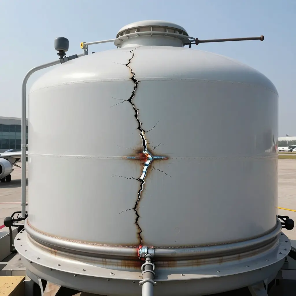
An airport crash tender water tank rarely fails in one dramatic event. It fails from the accumulation of millions of small ones.
Baffle cracking is mostly a fatigue problem. Repeated low-amplitude sloshing loads act on a structure that has already been in service for years; a single hydraulic overload is rarely the cause. Every time an ARFF vehicle accelerates, brakes, corners, or rolls over a runway joint, the water shifts and strikes the internal baffles. Each hit is small. Over a decade of ramp response, those cycles pile up at stress concentration points until a crack starts and grows to failure.
The mechanism in brief
- Sloshing puts kinetic energy into the baffle faces, which bend back and forth under cyclic stress.
- Stress concentration at baffle cutouts, corners, and weld toes pushes local stress well beyond nominal design levels.
- Weld fatigue and a brittle heat-affected zone make those joints the usual starting point for a crack.
- Corrosion and pitting lower fatigue strength and shorten the timeline.
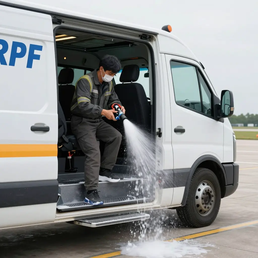
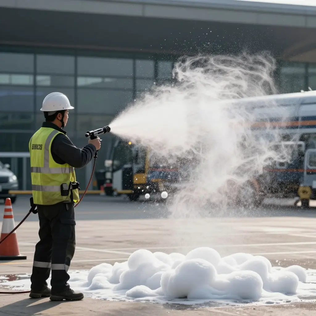
Sloshing fatigue also undermines downstream reliability: as baffle welds weaken, the water supply feeding other systems suffers. One example is foam proportioning drift that goes undetected on the ramp.
For fleet managers, the point is this: baffle cracks are a normal, cumulative result of service, not a manufacturing defect that appears overnight.
What this article covers
This article starts with how sloshing loads develop in real ARFF duty cycles, then looks at the stress concentration and weld fatigue hot spots where cracks usually begin. It covers inspection and NDT methods for finding fatigue cracking before a leak starts, and closes with design, fabrication, and maintenance practices that extend baffle life. The aim is practical: help ARFF fleet managers and crash tender maintenance engineers spot the pattern early and decide on repair or replacement with evidence in hand.

Reading the Schematic: How Sloshing Loads a Baffle
The diagram above shows the basic mechanism behind baffle cracking in a crash tender water tank. With fittings, framing, and external detail stripped away, the cross-section makes the physics easier to follow:
- The tank shell – the outer rectangle, the water tank wall, which carries the reaction loads the baffle passes on.
- The vertical baffle – the gray plate that splits the tank into two compartments. Its job is to limit how far the liquid surface can travel and to damp the momentum of a moving load.
- The shaded liquid block – the water or foam solution in the lower part of each compartment, at its static fill level.
- The curved arrow – the sloshing pressure wave. Under braking, cornering, or a sudden stop, the liquid surges toward one end of the tank and hits the baffle face as a concentrated dynamic pressure pulse.
Why This Matters
Each time that pressure wave hits, the plate flexes and the load travels through its welded or bolted connections into the tank shell. Repeated surges turn a single impact into millions of small stress reversals over the vehicle’s service life. At the baffle-to-shell joint, geometric discontinuities and weld imperfections concentrate stress, and that is where fatigue cracks start.
The schematic also explains why baffles fail after years rather than weeks. The load per event is modest; the number of cycles is not. Knowing this mechanism is what makes it possible to design baffles and inspection routines that last through the duty cycle.
Dynamic Sloshing Loads and Stress Concentration in Baffle Structures
When a crash tender is moving, the fluid in the tank does not travel as one rigid mass. Braking, turning, and acceleration let the water surge and oscillate, and the baffles break up that motion. The oscillating fluid puts cyclic pressure on the baffle face, rising and falling with each slosh, so the plate is loaded and unloaded again and again. Baffles are only partly submerged and are restrained along several edges, so pressure across the panel is uneven. That produces out-of-plane bending stress near the panel centers and membrane stress where the boundary restraints hold the plate in tension.
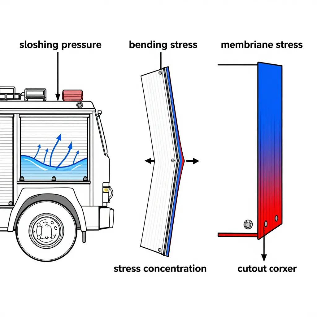
Bending stress dominates at the panel center and along supported edges; membrane stress builds near corners and welded boundaries, where the plate cannot flex freely. Wherever the geometry changes abruptly – stiffener-to-plate junctions, cutouts, lightening holes, access openings, and the weld toes that join baffle to shell – stress has to divert around the change. That diversion raises local stress above the nominal panel level, which is what stress concentration means. At weld toes, sharp cutout corners, and stiffener junctions the factor is usually several times nominal, and it acts exactly where the structure tolerates cyclic loading least.
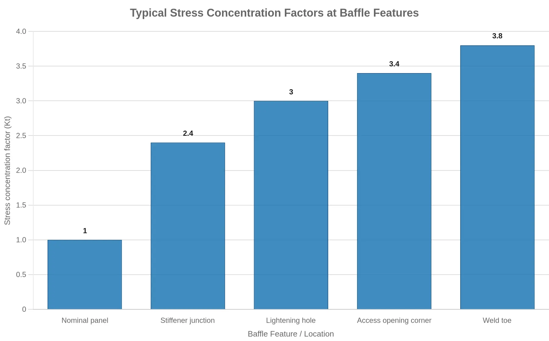
Every slosh cycle delivers one stress pulse. As operating hours add up, these regions see millions of load reversals. Once the local stress range exceeds the fatigue endurance of the material and its welds, small cracks form at the concentration site, usually a weld toe or a cutout corner, and then grow through the plate thickness under continued cycling. That is fatigue cracking, and it explains why baffle failures almost always start at geometric discontinuities rather than in flat panel areas where stress stays low and even. Knowing where those sites are is what makes it possible to inspect for cracking before it compromises the tank.
Cumulative Baffle Crack Growth vs. Sloshing Load Cycles
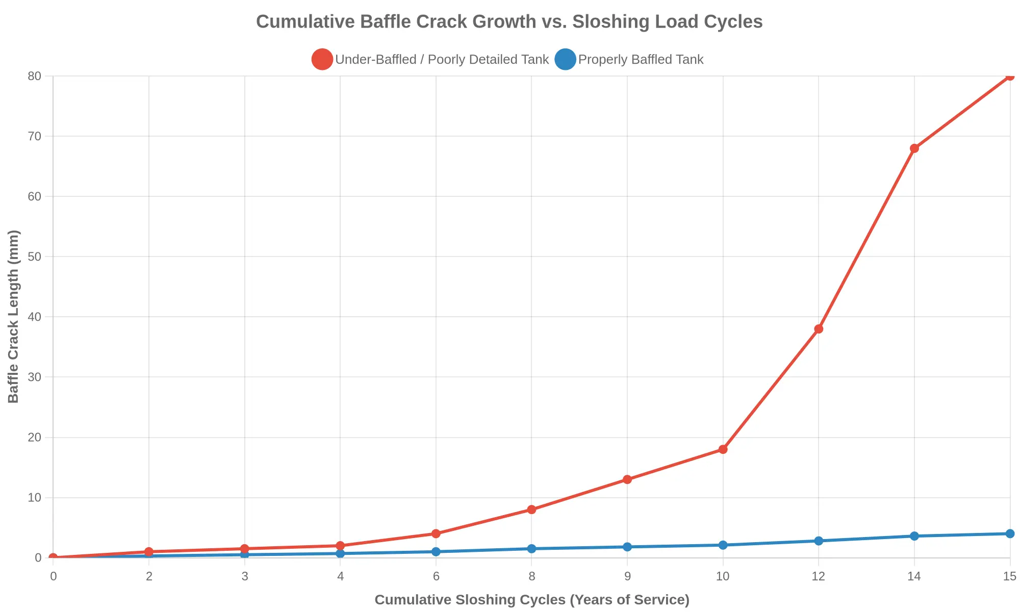
The chart above plots baffle crack length in millimeters against cumulative sloshing load cycles, given as years of service. The two curves show very different outcomes:
- Under-baffled / poorly detailed tank (red line): Crack growth follows a classic fatigue curve. For the first several years the crack creeps along almost invisibly – roughly 1-2 mm over the first four years – which is exactly why these defects escape routine inspection. Once the crack tip develops a sharp stress concentration, growth accelerates on its own. Between year 10 and year 15 the crack runs from about 18 mm to more than 80 mm.
- Properly baffled tank (blue line): With correctly sized baffles, good detailing, and sound weld geometry, the same sloshing energy is spread out instead of concentrated at one point. Crack growth stays nearly linear and negligible – under 4 mm even after 15 years.
Why the shape of the curve matters
This is not simple wear. It is fatigue damage piling up. Each sloshing cycle pushes a little cyclic stress into the baffle-to-shell weld. As the crack gets longer, stress intensity at the tip rises, and each cycle removes more material than the one before. That produces the concave-upward curve on the red line: the risk is not constant, it compounds.
| Years of Service | Under-Baffled Tank (mm) | Properly Baffled Tank (mm) |
|---|---|---|
| 0 | 0 | 0 |
| 4 | 2 | 0.7 |
| 8 | 8 | 1.5 |
| 10 | 18 | 2.1 |
| 12 | 38 | 2.8 |
| 15 | 80 | 4 |
The practical takeaway
The danger zone for fleet managers is the inflection point around year 8 to 10. A crack that measured a harmless 8 mm at year 8 can reach full penetration within a few more seasons of service. Scheduling inspections and weld-toe examinations before that point, not after, is what keeps a crash tender ready to respond. For a related failure mode that also develops quietly over time, see how foam proportioning drift goes undetected on the ramp.
Weld Fatigue Cracking: The Dominant Failure Mechanism at Baffle-to-Tank Connections
When baffles crack after years of service, the failure almost never starts in the base plate. It starts in the weld. The welded joints that tie each baffle to the tank shell and to the internal stiffeners carry the load from every slosh the tank experiences. Because those joints combine a geometric discontinuity with a heat-affected zone, they are where stress concentrates and where weld fatigue usually begins.
Why the Weld Becomes the Critical Point
A baffle lasts only as long as the connection that holds it. Every corner, edge, and stiffener attachment is a junction where plate thickness changes, the geometry steps, and residual welding stress is locked in. On every acceleration, braking, and cornering cycle, hydrodynamic pressure from the sloshing water pushes and pulls against the baffle surface. The bending moment that results goes almost entirely through the weld. That creates a stress concentration – a localized spike in stress intensity – right at the weld transition, where the metal is already the most metallurgically compromised.
How Cyclic Hydrodynamic Loads Drive Crack Initiation
Sloshing is cyclic by nature. A crash tender may log thousands of acceleration and deceleration events over its service life, and each one reverses the load on the baffle connection. Individually modest, these cycles add up as fatigue cracking. Micro-cracks form at the weld toe (where the weld face meets the base metal) or at the weld root (the unexposed region beneath the weld pass), where stress concentration is highest and inspection is hardest. Given enough cycles, a microscopic defect becomes a measurable crack.
Weld Geometry, Undercut, and Lack of Penetration
Weld quality sets how quickly fatigue cracking begins:
- Poor weld geometry – Excessively convex or concave beads, abrupt toe angles, or uneven reinforcement raise the stress concentration factor at the toe and cut the number of cycles needed for a crack to start.
- Undercut – A groove melted into the base metal along the weld edge works as a built-in stress raiser and a crack starter.
- Lack of penetration – Incomplete fusion at the weld root leaves an unfused gap that acts like a sharp internal notch, often starting root cracks that cannot be seen from inside the tank.
Every one of these defects shortens the fatigue initiation phase, which is why tanks built to the same drawing can fail years apart when weld quality differs.
From Initiation to Propagation to Through-Thickness Failure
Fatigue cracking moves through recognizable stages. In initiation, micro-cracks form at a toe or root defect but stay microscopic and undetectable. During propagation, each slosh cycle drives the crack front a little deeper through the weld metal and heat-affected zone. Because the crack tip concentrates stress further, growth speeds up as the crack lengthens. Finally the crack becomes through-thickness, penetrating the full baffle plate or shell wall so water can bypass the baffle or leak from the tank. At that point the sloshing load is no longer restrained, and adjacent welds start carrying loads they were never designed for, which often leads to cascading failures.
For maintenance planning, the sequence matters: by the time a through-thickness crack appears, the mechanism has been active for years. Finding weld toe and root defects early, before propagation begins, is the most effective way to extend baffle life and keep crash tenders in service.
When teardown inspection turns up cracking, the location usually points to the mechanism behind it. The table below maps common baffle and attachment locations inside a crash tender water tank to the dominant failure mode, the load that drives it, and the practical way to catch it before it becomes a leak.
| Baffle Location | Dominant Failure Mode | Primary Load Source | Recommended Detection Method |
|---|---|---|---|
| Baffle-to-tank-shell weld | Fatigue cracking along the weld toe | Longitudinal sloshing pressure cycling against the shell | Visual inspection plus dye penetrant testing during tank entry |
| Baffle-to-stiffener junction | Stress-concentration cracking at the weld intersection | Bending and shear transferred from panel deflection | Phased-array ultrasonic weld inspection |
| Baffle cutout / access opening | Crack initiation at sharp corners of the opening | Membrane stress concentration at the geometric stress riser | Magnetic particle inspection of the radii |
| Drain or vent penetration | Weld-root cracking around the nozzle | Local pressure fluctuation and turbulent flow at the opening | Close visual inspection with dye penetrant |
| Baffle base connection | Fatigue cracking where the baffle meets the tank floor | Repeated slosh-induced bending at the base restraint | Tank-floor ultrasonic thickness mapping plus visual survey |
One pattern runs across the table. Surface-breaking defects at weld lines are well suited to dye penetrant and magnetic particle methods, while junction and base failures that hide within section thickness need volumetric techniques such as phased-array ultrasonic testing. Matching the detection method to the expected location is what turns a routine inspection into a real root-cause investigation.
Contributing Factors That Accelerate Baffle Cracking
Several engineering and operational factors combine to speed up baffle fatigue cracking in airport crash tenders. A root-cause analysis that ignores them will miss the point.
-
Repetitive braking and cornering cycles: Every emergency response, driver-training run, and repositioning move throws the water mass sideways against the baffles. Those reversing stress cycles build fatigue damage far faster than steady-state travel ever would.
-
Chronic partial-tank operation: Running under-filled is one of the most damaging habits in ARFF service. A partly filled tank lets the free surface travel farther and strike the baffles with more momentum than a full or empty tank.
-
Stiffener spacing: Wide stiffener spacing lowers panel stiffness and shifts vibration modes toward the sloshing frequencies, concentrating dynamic stress at the panel-to-stiffener junctions where cracks typically start.
-
Weld quality: Undercut, incomplete penetration, porosity, and other weld discontinuities act as built-in stress risers that seed fatigue cracks at the baffle-to-shell and baffle-to-stiffener connections, the most common failure sites in service.
-
Plate thickness: Thin baffle and shell plate flexes more under sloshing pressure, raising cyclic stress amplitude and lowering the number of cycles the structure can take before cracking develops.
-
Galvanic and corrosion-assisted cracking: Dissimilar-metal couples, stagnant water, and attack around welds drive localized corrosion that removes load-bearing section. Combined with sustained tensile stress, that can lead to stress-corrosion cracking.
-
Sloshing resonance and fill-to-discharge cycling: When baffle stiffness lines up with the tank’s natural sloshing frequency, or the tank is repeatedly filled and dumped at high rate, cyclic loading intensifies and fatigue life drops accordingly.
Where the Cracking Actually Starts
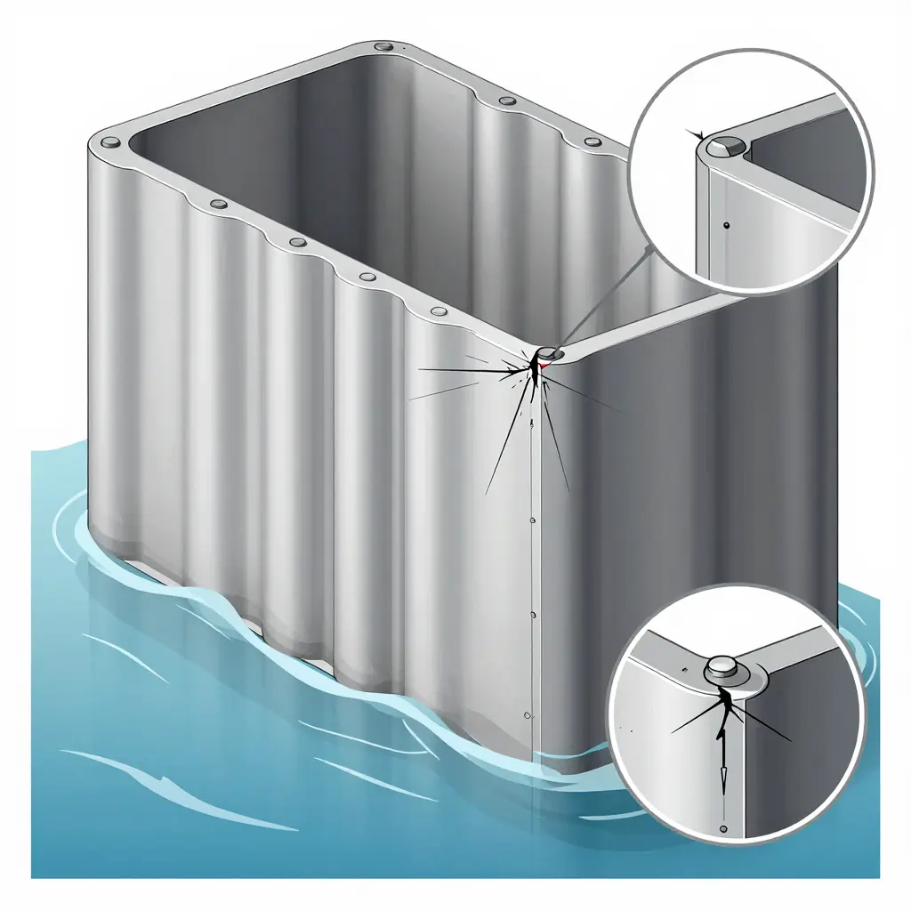
To see why tank baffles fail, it helps to look closely at the geometry. The schematic above shows a magnified cross-section of a baffle plate welded to the tank wall. The baffle is a vertical divider inside the water tank, attached to the shell with a fillet weld. The critical zone is the weld toe – the sharp transition where the weld bead blends into the baffle plate surface.
Over years of sloshing, every acceleration, braking event, and hard steering input pushes the water mass against the baffle. That load goes straight through the weld toe, which acts as a stress concentration point. The curved dashed arrow in the diagram traces a small crack starting at that toe and working through the plate thickness – quietly, cycle after cycle, until the baffle no longer holds.
Other tank-adjacent failures follow the same pattern. Foam system failures often go unnoticed until they matter most (see how foam proportioning drift stays hidden on the ramp), and baffle weld fatigue develops out of sight until it becomes structural.
Material Selection and Fabrication Quality: What Really Determines Baffle Fatigue Life
Two crash tenders can leave the same production line with baffles cut to identical dimensions, yet one survives a decade of sloshing and the other shows through-thickness cracking in three years. The difference usually sits below the surface, in the metallurgy of the base metal and the integrity of the welded joint, not in the drawing tolerances.

Steel Grade and Base-Metal Toughness
Baffle plate is usually a weldable structural or pressure-vessel steel, such as ASTM A36, A572 Grade 50, or a normalized grade like ASTM A516. For fatigue, the controlling properties are toughness and cleanliness – low sulfur content and fine grain size – not yield strength. Higher-strength grades raise static capacity but can cut ductility, narrowing the plastic zone that blunts a crack tip. A brittle, coarse-grained heat-affected zone turns a small notch into a fast-propagating crack.
Plate Thickness and Stiffness
Thickness governs both membrane stress and the stress concentration at a discontinuity. A thin baffle deflects more under sloshing pressure, which concentrates bending stress at the first restraint – the weld line. Adding thickness lowers nominal stress but also raises joint restraint and the thermal gradient during welding, which can sharpen residual stress fields instead of easing them. Thickness has to match local hydrodynamic pressure and the stiffness of adjacent stiffeners.
Corrosion Allowance and Wall Loss
Baffles in water and foam service see pitting and general corrosion, particularly at crevices and weld toes where oxygen differential cells form. A corrosion allowance (often 1.0-3.0 mm) is added to design thickness. Once it is consumed, effective thickness falls to the minimum design value and below, raising stress at the weld toe. Pitting under foam residue eats into the fatigue notch margin, so allowance is no substitute for coating integrity and drainage.
Weld Procedure and Heat Input
Fatigue cracks in tanks almost always start in the weld metal and its heat-affected zone. The qualified welding procedure specification (WPS) sets current, travel speed, and heat input. Too much heat input produces coarse grain and a wide HAZ; too little causes lack of fusion and cold lap. Both leave sharp geometric discontinuities that act as crack starters.
Weld Toe Geometry and Grinding
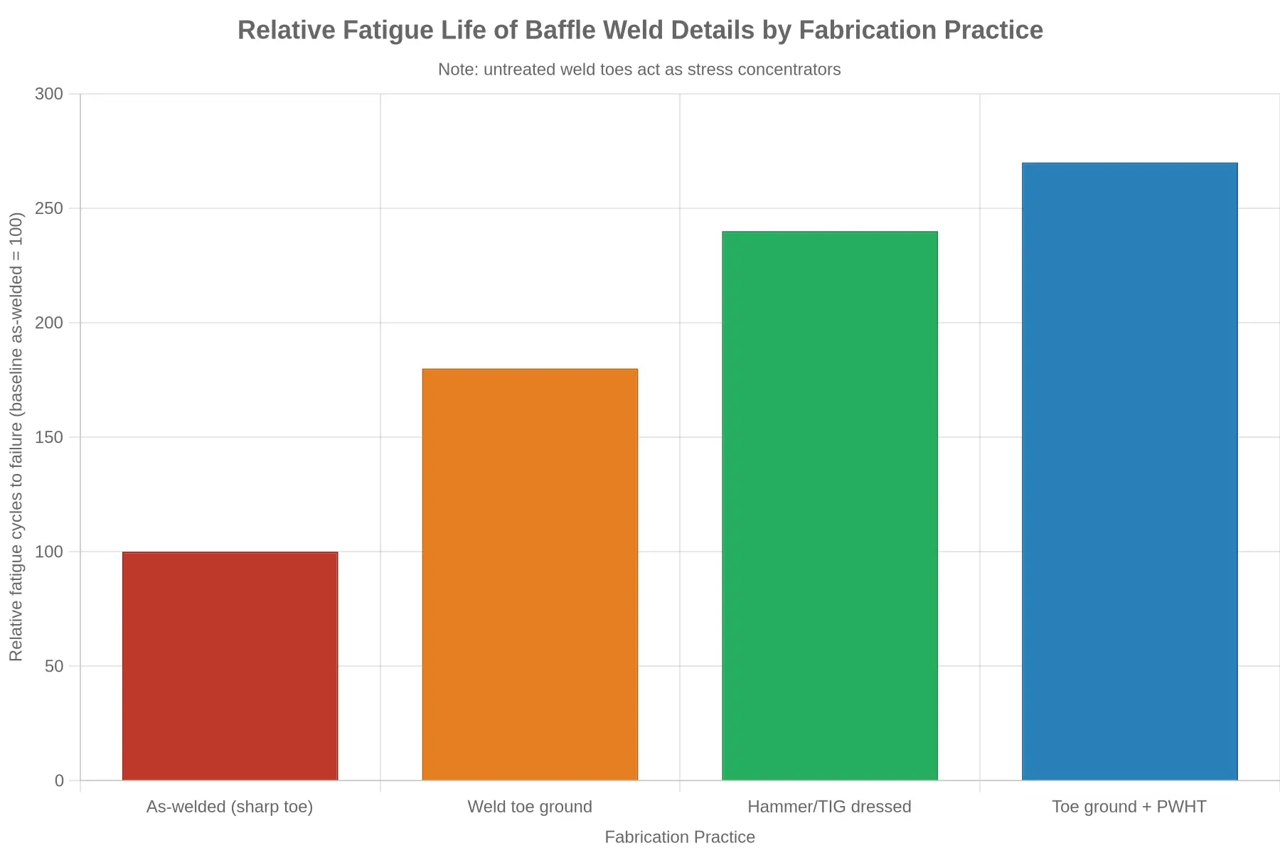
The weld toe has more influence than any other feature. An as-welded toe has an effective radius under 0.5 mm, which produces a stress concentration factor (Kt) of 3 or more. Grinding removes the sharp transition, enlarges the toe radius, and typically improves fatigue life by a factor of 2 to 3. TIG dressing or hammer peening achieves similar gains by reshaping the toe and introducing compressive residual stress.
Post-Weld Treatment and Residual Stress
Welding leaves tensile residual stress approaching yield at the weld line, exactly where sloshing adds cyclic stress. Post-weld heat treatment (PWHT) relaxes that stress, while mechanical treatments such as needle peening or ultrasonic impact treatment introduce beneficial compressive stress at the surface. Without relief, mean stress stays high and fatigue life drops even when the geometry is nominally correct.
| Fabrication Variable | Typical Specification | Effect on Baffle Fatigue Life |
|---|---|---|
| Steel grade / toughness | A36, A572 Gr 50, A516 | Higher toughness resists crack propagation |
| Plate thickness | Matched to hydrodynamic pressure | Lower stress, but higher joint restraint |
| Corrosion allowance | 1.0-3.0 mm | Preserves section; delays stress rise at weld toe |
| Weld heat input | Per qualified WPS | Controls HAZ grain size and defect formation |
| Weld toe radius | Ground or dressed toe | Raises toe radius, cuts Kt, adds 2-3x life |
| Post-weld treatment | PWHT, peening, UIT | Lowers tensile/induces compressive residual stress |
Why a Dimensionally Correct Baffle Still Cracks
A baffle can meet every drawing dimension – square, flat, bolt holes aligned – and still crack early. Dimensional inspection cannot detect a sharp weld toe, an undercut, an unfused root, coarse HAZ grain, or tensile residual stress. These fabrication-level discontinuities act as local stress concentrators wherever cyclic sloshing stress peaks. Fatigue is a local phenomenon: the crack forms at the worst 0.5 mm, not at average plate thickness. That is why two “identical” baffles end up with different service lives, and why fabrication quality control – not dimensional tolerance – governs fatigue durability.
Operational and Mission-Profile Drivers of Sloshing Fatigue
Baffle cracking rarely comes from a single overstress event. It comes from how a crash tender is operated day after day, year after year. The dominant driver is not peak load but the sheer number of low-amplitude sloshing cycles the tank shell and baffle welds accumulate over a service lifetime.
Operating Patterns That Accumulate Cycles
- Frequent partial-tank operation. Tenders are usually topped off only enough to meet response requirements. A half-full tank leaves a large free liquid surface, so every acceleration and turn sends fluid surging across the baffle faces.
- High-cycle response runs. On alarms, trucks leave, run a short distance, and return, often dozens of times a year. Each run produces repeated fill-and-slosh loading cycles rather than a single sustained event.
- Rough-terrain and off-runway travel. Turf, gravel, and graded shoulders add continuous random excitation. The high-frequency jostling generates many small-amplitude waves that flex baffle-to-shell welds at low stress but high repetition.
- Rapid acceleration and braking. Heavy braking on the apron and hard acceleration on response push slug loads forward and back, loading welds in alternating tension and compression.
- Long idle periods between high-demand events. Idle time does not reset the fatigue process. It does nothing to relieve micro-damage that has already accumulated.
Each event is mild on its own. Collectively, over a 15- to 20-year life, these patterns can total millions of low-amplitude sloshing cycles. Because fatigue damage is cumulative and nonlinear, thousands of small cycles at stress levels well below yield can still initiate and propagate cracks at stress concentrations in baffle welds. This is why a tender can pass every static inspection and still develop leaks years later: the damage is driven by operational repetition, not by any single incident.
Inspection and Detection Methods for Baffle Fatigue Cracks
Baffle fatigue cracking rarely announces itself with a visible rupture. Cracks usually nucleate at weld toes and other stress concentration points, where the baffle-to-shell and baffle-to-baffle joints absorb millions of low-amplitude sloshing cycles across the vehicle’s service life. Because a crack can stay tight, surface-closed, and sealed while the tank is cool, the defect often remains invisible until a full-thickness rupture triggers leakage during a callout. Effective detection therefore relies on a layered strategy that pairs accessible visual checks with targeted nondestructive testing (NDT) and indirect environmental monitoring.

Visual inspection of accessible weld zones
Start every inspection with direct visual testing (VT) of all reachable internal and external weld zones. Where access hatches, manways, or removable baffle sections permit entry, inspect the full weld toe around each baffle attachment.
Watch for:
- Hairline cracks radiating from weld toes, especially at the corners of baffle-to-shell junctions
- Rust staining, paint blistering, or streaking that traces a hidden crack path
- Damp seams or weeping beads seen immediately after draining or during a fill test
- Local distortion, oil-canning, or ripples in the baffle plate that signal loss of stiffness
Document each finding by location and photograph it against a fixed reference so successive inspections can be compared over time.
Dye penetrant and magnetic particle testing
When VT flags a suspect weld, surface NDT confirms whether an indication is a true surface-breaking crack.
| Method | Best suited to | Detects | Access required | Notes |
|---|---|---|---|---|
| Dye penetrant (PT) | Stainless and non-ferrous tank shells | Surface-breaking cracks and porosity | Clean, dry, reachable surface | Two-part penetrant/developer; fluorescent version improves sensitivity |
| Magnetic particle (MT) | Ferrous carbon-steel tanks | Surface and shallow subsurface defects | Clean surface; magnetizing equipment | Fast, low cost; not valid on austenitic stainless |
| Ultrasonic (UT) | All weld regions, including thick plate | Internal and near-surface cracks, remaining ligament | Probe access to the weld region | Shear-wave angle beam or phased array for the heat-affected zone |
Both PT and MT demand a clean, dry, contaminant-free surface, and both work best as screening methods: size any indication with a volumetric technique before deciding on a repair.
Ultrasonic inspection of weld regions
UT detects cracks before they break the surface and measures how much sound material remains. Angle-beam shear-wave probes scan the heat-affected zone (HAZ) at the baffle-to-shell weld, while phased array UT (PAUT) maps the full weld profile and produces a readable depth-and-length image. Use UT when a surface method returns an indication, or when you want to establish a thickness and defect baseline before any crack becomes surface-visible.
Monitoring for water ingress and tank deformation
Structural cracks often show themselves indirectly first. Watch these signals between formal inspections:
- Recurring damp patches, corrosion, or water pooling beneath the tank
- A crack that weeps during operation but seals once the tank cools
- Gradual deformation, bowing, or a change in the tank’s flatness
- Pressure or vacuum decay during a routine leak test
Record fill and drain behavior, along with any unexplained change in capacity, as an early-warning indicator.
From detection to condition-based maintenance
Early detection converts baffle cracking from a reactive repair into a planned, condition-based activity. By baselining weld condition and tracking indications over time, maintenance planners can:
- Assign severity grades, from a surface indication to a through-crack, that map to defined response windows
- Schedule repair during known downtime rather than after an unplanned leak grounds the vehicle
- Justify inspection intervals with measured crack growth instead of fixed calendar cycles
For fleet managers, the payoff is a crash tender that stays in service: weld inspections become a data-driven input to budget and downtime planning, not a surprise line item triggered by a ramp-side failure.
Prevention and Mitigation Measures to Extend Baffle Service Life
Baffle fatigue cracking is a predictable failure mode, but not an unavoidable one. Each measure below targets a specific root cause, from initial design through in-service operation.

Improved Baffle and Stiffener Design
Cracking usually starts where geometry concentrates stress: welded corners, sharp cutouts, and undersized stiffeners. Redesigning baffles with generous fillet radii, continuous stiffener runs, and graduated plate thickness spreads load over a wider area.
That lowers the stress amplitude at any single point, keeping the local fatigue limit above the cyclic loads that sloshing generates. Finite element analysis (FEA) confirms hot spots before fabrication begins.
Weld Toe Treatment
Weld toes are the classic initiation site because they combine residual tensile stress with a geometric notch. Grinding, TIG dressing, or peening the toe smooths that transition and introduces compressive residual stress at the surface.
The result is delayed crack initiation and slower early crack growth, which extends the number of slosh cycles the baffle can tolerate.
Optimized Fill-Level Operating Procedures
Partial fill levels that align with the tank’s natural slosh frequency produce the largest fluid forces. Procedures that favor fuller fills, or deliberate lower levels, and that avoid sustained part-load travel reduce peak dynamic pressure on the baffles.
Cutting load amplitude is the most direct way to slow fatigue accumulation.
Inspection-Led Maintenance Programs
Fatigue is cumulative, so early detection changes the outcome. Scheduled non-destructive testing (dye penetrant, magnetic particle, or ultrasonic) at known hot spots, paired with documented crack-growth tracking, turns maintenance from reactive to predictive.
Small cracks can then be ground out and re-welded during planned downtime rather than forcing emergency repairs.
| Measure | Fatigue Root Cause Addressed | Primary Benefit |
|---|---|---|
| Improved baffle and stiffener design | Stress concentration at geometric discontinuities | Lowers peak local stress |
| Weld toe treatment | Weld toe notches and residual tensile stress | Delays crack initiation |
| Optimized fill-level procedures | High-amplitude slosh loads at resonant fill levels | Reduces cyclic load amplitude |
| Inspection-led maintenance | Cumulative, hidden crack growth | Enables early, planned intervention |
These measures reinforce one another, and they rest on the same reliability discipline that keeps the whole truck in service. As with broader ARFF system reliability problems, such as undetected foam proportioning drift on the ramp, the fix is knowing where the system quietly degrades before it fails.
Frequently Asked Questions: Crash Tender Baffle Cracking
Why do baffles crack even when the tank looks fine?
Baffles sit inside the tank, so a walk-around rarely reveals damage. Sloshing forces concentrate at the weld toes where the baffle meets the shell, and fatigue cracking starts there as a hairline defect and slowly grows. The outer skin can look pristine while internal baffle welds accumulate stress cycles. A clean exterior does not mean sound baffles.
Why is sloshing such a problem in fire apparatus?
Water and foam have mass. During braking, cornering, and acceleration the liquid surges fore and aft and slams into the baffles. Each surge applies a stress cycle to the welds and surrounding plate. Over years of ramp duty, that repetition drives weld fatigue until a crack starts and grows.
How long until baffle cracks typically appear?
Duty cycle sets the clock, not age alone. Most fatigue cracking appears after roughly 8 to 15 years of service, depending on mileage, road roughness, and fill level. Tenders that run partially loaded accumulate stress cycles faster and may crack sooner than those kept at a consistent high fill.
Does fill level affect baffle fatigue?
Yes. A partially filled tank has the largest free surface area, which allows the most sloshing energy and the highest cyclic stress on the baffles. Running consistently at full or near-empty reduces sloshing amplitude and cyclic load. Where the mission allows, managing fill level is a practical way to slow fatigue.
Can baffle cracks be repaired in the field?
Minor cracks can sometimes be stop-drilled and re-welded in the field, but only with the right procedure: grind the crack out to sound metal, apply proper preheat, use the specified filler, and inspect after welding. Extensive weld fatigue, or cracking at stress concentration points, usually means removing the tank and re-fabricating the baffle-to-shell joint.
How often should baffles be inspected?
Treat baffle inspection as scheduled maintenance, not a reaction to failure. Inspect internally at least once a year and after any collision, rollover, or hard braking event. Combine visual internal inspection with dye penetrant or ultrasonic testing on suspect welds, and track findings over time so you can predict a failure instead of discovering one.
Practical Takeaways
| Question | Practical Action |
|---|---|
| Hidden cracks | Perform internal, weld-focused inspection |
| Fill level | Avoid chronic partial loading where possible |
| Field repair | Limit to minor cracks with certified procedure |
| Inspection cadence | Annually and after any incident |
| Crack tracking | Log weld fatigue findings per unit |
Baffle cracking is a fatigue problem, not a cosmetic one. Building internal weld inspection and fill-level discipline into an ARFF fleet program keeps crash tenders available and stops sloshing-driven failures from grounding a unit when response capability matters most.
Conclusion: Keeping Baffles, and Missions, Ready
Nothing mysterious causes baffle cracking in airport crash tender water tanks. It is a predictable fatigue phenomenon. Every acceleration, brake application, and turn sends the water mass surging against the baffles, and each cycle delivers a small, cumulative load. Where a baffle meets the tank shell, or a stiffener meets a weld toe, the geometry concentrates that load into a narrow band of material. Over thousands of operating hours, the repeated stress works at the weld and heat-affected zone until a crack initiates and grows.
Because the mechanism is predictable, the response can be too. Baffle service life comes down to four controllable inputs, and no single one makes up for a weakness in another:
- Design – baffle spacing, thickness, and joint geometry that keep stress concentration out of vulnerable regions.
- Fabrication quality – sound welds, proper penetration, and controlled heat input that resist fatigue initiation.
- Operating practice – realistic fill levels and driving behavior that reduce the magnitude and frequency of slosh cycles.
- Inspection – routine visual, dye penetrant, and structural checks that catch hairline cracking before it reaches critical length.
Treat them as one system and the tank becomes a managed asset instead of a slow-motion failure. The same discipline reaches past the tank: ARFF maintenance and asset management depend on understanding how environmental and operational stress shortens component life across the vehicle, from the water tank to the foam system. For a closer look at how temperature swings degrade foam concentrate over time, see this analysis of why temperature swings shorten foam agent shelf life.
The path forward is fairly clear. As airports modernize fleets and tighten readiness targets, crash tenders will be judged on how fast they respond and on how well every system holds up between responses. Designing for fatigue, building for weld integrity, operating within realistic limits, and inspecting on schedule will keep baffles intact and tanks sound through the years of sloshing still to come.