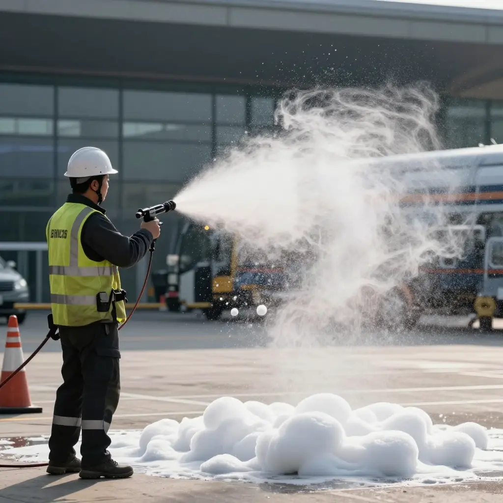
Understanding Airport Crash Tender Foam Proportioning and the Problem of Drift
Airport crash tender foam proportioning is the process an ARFF vehicle uses to meter foam concentrate into a pressurised water stream so the finished foam reaches a specified concentration, usually 1%, 3%, or 6%. When that metering slowly departs from its target, the result is foam proportioning drift: a cumulative gap between the concentrate percentage the system actually delivers and the one it was calibrated to deliver. Drift raises no alarm and lights no warning lamp, and nothing about how the truck drives or discharges looks different. That is why it survives routine ramp operations.
Four terms carry most of the discussion. Foam concentrate is the agent carried onboard; foam proportioning is the metering action that dilutes it; the induction ratio (also called the proportioning ratio) is the volumetric relationship between concentrate and water; and the setpoint is the target the system is calibrated to achieve. A drifted system still flows and still passes a visual check, but delivers foam well outside its setpoint, which costs extinguishing performance on the day it is needed.
How ARFF Foam Proportioning Systems Work
An ARFF foam proportioning system injects foam concentrate into the water stream at a set ratio before the solution reaches the branch. With the right ratio you get finished foam that blankets a fuel spill; with the wrong one you can still see white foam at the nozzle while the fire burns underneath.
The function is simple; the plumbing is not. Water source, proportioner, concentrate tank, metering valve, and discharge point all have to agree on flow and pressure at the same moment.
Venturi and induction proportioners
The classic design uses the venturi principle. Water accelerates through a narrowed throat inside an eductor, local pressure drops, and concentrate is drawn from the tank into the stream — foam concentrate induction.
A metering valve (or proportioner) sets how much concentrate is admitted. Because the draw depends on a stable pressure drop, a change in nozzle flow, hose length, or pump output shifts the effective ratio.
Balanced-pressure and around-the-pump systems
Balanced-pressure proportioners use a diaphragm valve to match concentrate pressure to water pressure, which holds the ratio steady across a wide flow range. The design is common on modern crash tenders because it tolerates a monitor and several handlines flowing at once.
Around-the-pump systems inject concentrate on the suction side of the fire pump, so the pump meters the blend mechanically. The mix is consistent, but the balance line and check valves need careful maintenance.
Foam concentrate types
AFFF (aqueous film-forming foam) spreads a thin film over hydrocarbon fuels and is specified at 3% in most ARFF applications. AR-AFFF adds a polymer so the foam tolerates polar solvents such as ethanol and alcohol-blended fuels, usually at 3% or 6%.
Fluorine-free foams are being adopted to meet environmental rules, and they often need tighter proportioning than legacy concentrates because burnback performance is more sensitive to the ratio.
Target induction percentage and expansion ratio
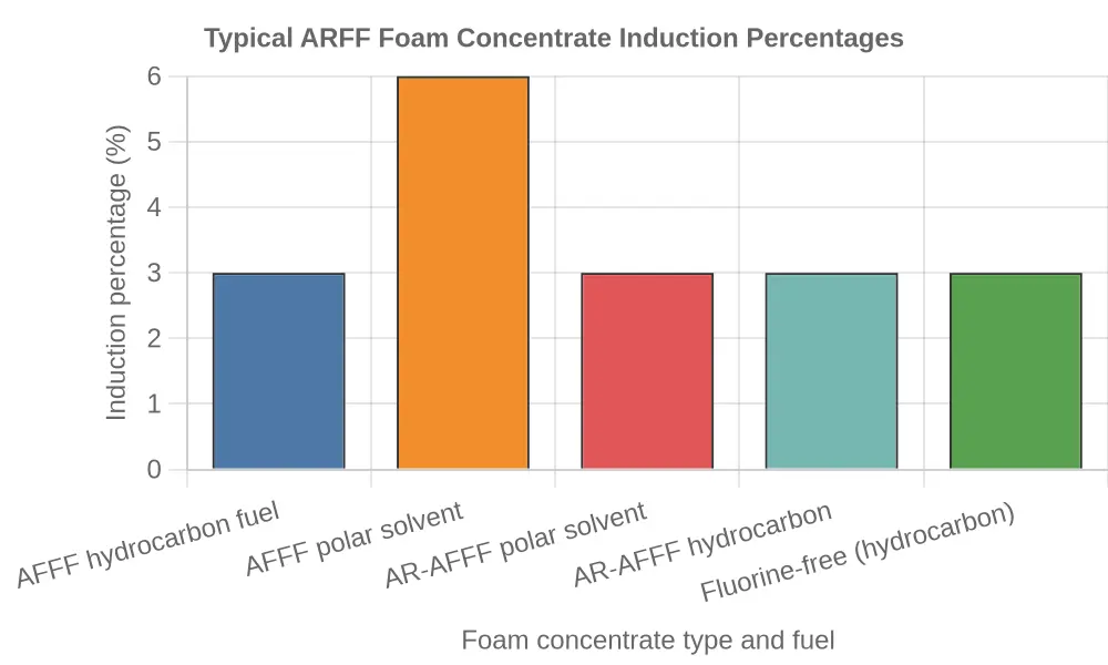
Most ARFF operations run 3% foam concentrate induction on hydrocarbon fuel fires. Polar solvents need an alcohol-resistant concentrate, which is listed at 3% or 6% depending on the product, and some fluorine-free foams are specified at 3% as well. Match the ratio to the concentrate’s approval listing.
The expansion ratio — finished foam volume divided by foam solution volume — determines whether the discharge is low-, medium-, or high-expansion. Low-expansion foam dominates runway and fuel-spill work; medium and high expansion suit enclosed spaces.
Main proportioning architectures at a glance
- Venturi / induction proportioner: a pressure drop across an eductor pulls concentrate into the water stream; simple and flow-sensitive.
- Balanced-pressure proportioner: a diaphragm valve equalizes water and concentrate pressure for a stable ratio over a wide flow range.
- Around-the-pump system: concentrate is injected on the pump suction side, so the fire pump meters the finished solution.
- Direct-injection system: an independent pump doses concentrate into the discharge line under electronic control, which lets the controller adjust induction as flow changes.
Typical induction percentages by concentrate
| Foam concentrate and fuel | Target induction |
|---|---|
| AFFF – hydrocarbon fuel | 3% |
| AR-AFFF – polar solvent (3% listing) | 3% |
| AR-AFFF – polar solvent (6% listing) | 6% |
| AR-AFFF – hydrocarbon fuel | 3% |
| Fluorine-free – hydrocarbon fuel | 3% |

Every one of these architectures is a mechanical agreement between flow, pressure, and viscosity. When one of the three shifts — a worn eductor, a sticking metering valve, a thickened concentrate — the proportioner keeps working, just not at the percentage you think.
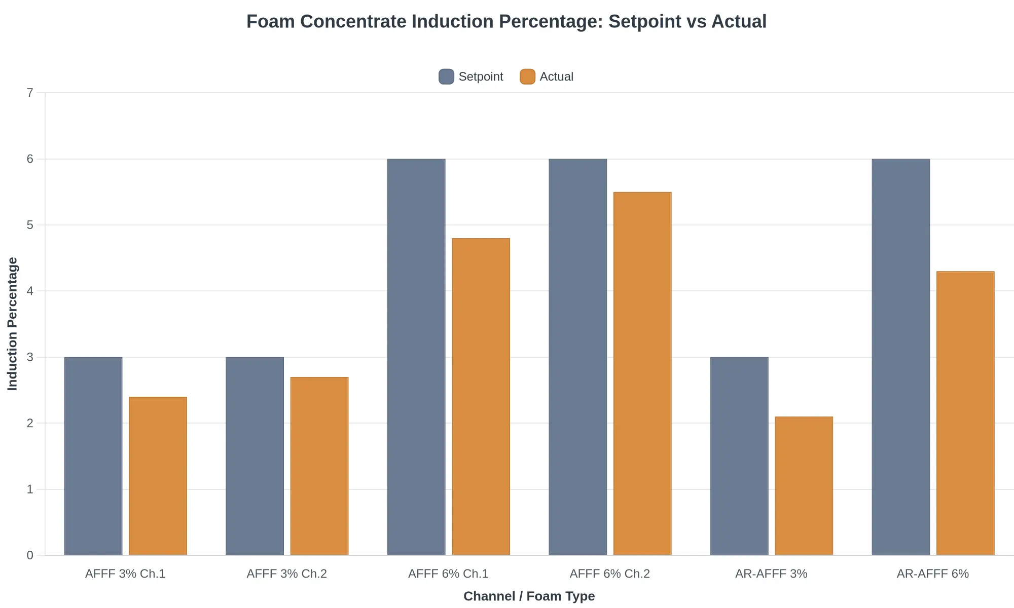
The chart below compares intended setpoint with measured induction across representative ARFF proportioner channels.
Why Proportioning Drift Stays Hidden on the Ramp
Undetected foam proportioning drift persists mainly because nothing measures concentration inline and continuously. A proportioning system can command a target ratio, but it cannot confirm the ratio it actually delivered unless a sensor measures foam concentration in the discharge stream in real time. In most ARFF configurations no such sensor sits between the concentrate tank and the nozzle, so the control logic compares the commanded value with an assumed one. The system cannot report an error it was never designed to sense, and the gap between set point and actual output stays invisible to the operator.
Without an inline metering device, ratio control depends on pre-set metering valves built to deliver a fixed proportion under assumed flow and pressure. A venturi or balanced-pressure proportioner regulates concentrate flow mechanically, so the ratio is inferred from valve position and differential pressure instead of measured. The inferred value is treated as the true value, so a unit that has shifted away from its reference point still displays a normal-looking set point. The design assumes stability rather than testing for it.
Periodic rather than continuous proportioner calibration compounds the problem: the interval between checks is a blind window. A venturi throat erodes, a diaphragm spring fatigues, a seal deteriorates, a metering orifice drifts. Each part keeps working, just not the way it did, so no discrete fault crosses a threshold that would trip an alarm.
Concentrate viscosity adds a variable static inspection cannot capture. Viscosity changes with temperature and age, and a given orifice passes different flow rates as it shifts, so the true ratio changes without any visible setting changing. There is no fault code and no external symptom, so the system looks normal during routine checks. Visual inspection and static functional tests confirm that components exist, move, and hold position. They do not measure delivered concentration, which is exactly what drift corrupts. A visual check cannot catch a mix ratio that has quietly moved.
Proportioning System Flow: Where Drift Begins
A simplified schematic of the proportioning path — water pump, proportioner/eductor, discharge nozzle. The red marker flags the interface between the metering valve and the induction line, where drift most often develops unobserved.

Common Contributors to Foam Proportioning Drift
- Eductor wear erodes internal clearances, reducing induction efficiency and shifting the delivered concentrate ratio.
- Clogged metering orifices restrict concentrate flow, causing lean mixtures that degrade extinguishing performance.
- Incorrect concentrate viscosity from temperature swings alters flow characteristics through fixed orifices and pumps.
- Air leaks in the induction line break the vacuum, disrupting accurate foam concentrate pick-up.
- Sensor placement near turbulence or bends produces readings that misrepresent true proportioning ratios.
- Adjustment drift from sustained vehicle vibration gradually shifts calibrated set points out of tolerance.
- Contaminated concentrate or hard water alters surface tension, changing expansion and drainage behaviour.
- Pump wear reduces discharge pressure stability, undermining the pressure balance that eductors rely upon.
These contributors rarely act alone. They compound until small errors mask one another during routine checks, which is why consistent proportioning maintenance is the practical way to catch the combined effect before it reaches the ramp.
Comparison Table: ARFF Foam Proportioning Drift Symptoms and Root Causes
The table below pairs common drift symptoms with the root cause, the component that drives each fault, and the check a technician can use to confirm it.
| Observable Symptom | Likely Root Cause | Affected Proportioning Component | Recommended Verification Method |
|---|---|---|---|
| Weaker foam blanket and poor bubble structure | Foam solution inducted too lean (low concentrate percentage) | Proportioner metering orifice | Draw a sample at the test point and confirm foam concentrate percentage with a refractometer |
| Longer knockdown time on a live fire | Expansion ratio below the specified range | Balanced-pressure proportioner valve | Perform a flow-rate and expansion-ratio field test at rated discharge |
| Inconsistent expansion across outlets | Worn or mismatched air-aspirating nozzle | Nozzle and foam tube assembly | Inspect each nozzle and compare discharge flow and expansion outlet by outlet |
| Foam ratio drifts as engine RPM changes | Worn water-pump impeller or unstable discharge pressure | Water pump and pressure-control valve | Monitor discharge pressure and induction ratio across the full engine RPM range |
| Incorrect ratio occurs only at high flow | Fouled or undersized metering orifice | Metering orifice and inductor | Bench-test orifice flow at the rated gpm and compare against the datasheet |
| Foam appears too rich, with slow drainage and sticky residue | Stuck or over-travelling proportioning control valve | Proportioning control valve and actuator | Cycle the valve and verify stem position and position-feedback signal |
| Unstable electronic ratio readings and drift alarms | Faulty flow sensor or calibration drift | Electronic controller and flowmeter | Run a calibration check and read the controller diagnostic log |
Industry Calibration and Inspection Guidance: What the Standards Suggest
Public industry guidance treats ARFF foam proportioning calibration as scheduled maintenance, not a one-off commissioning task. ARFF maintenance frameworks based on NFPA practice, along with service literature from proportioner and vehicle manufacturers, say the same thing: verify periodically, after any repair or component replacement that affects the foam system, and whenever performance is in doubt. Proportioning verification compares the delivered concentrate percentage with the design or target concentration across the system’s operating range, using recognised methods such as refractive index or conductivity measurement. Recommended intervals vary with jurisdiction, vehicle type, and duty cycle, and no single number covers every fleet. Consult the vehicle’s maintenance manual and the applicable service documentation before setting a calibration schedule.
- Verification is scheduled work. Proportioning checks recur at defined intervals and after any repair that could disturb the system.
- Intervals are vehicle- and authority-specific. Duty cycle, foam type, system design and local regulation all influence the recommended frequency, so a generic figure should not override the manual.
- Testing methods must suit the foam and system. Recognised techniques such as refractive index or conductivity testing confirm the concentrate percentage actually delivered.
- Documentation supports accountability. Records of each calibration and verification event help demonstrate compliance and reveal slow drift that single checks may miss.
- The manufacturer has the final say. The vehicle’s maintenance manual and the relevant service schedule remain the authoritative source for the correct calibration and inspection interval.
Foam Proportioning Drift Over Service Life
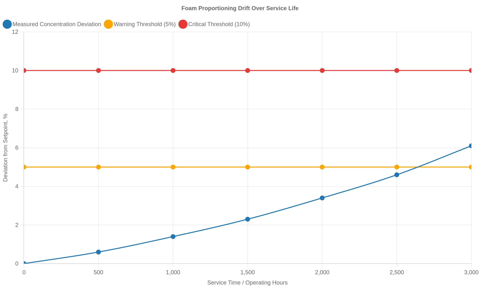
Drift accumulates over service hours, staying under the warning threshold until performance is already degraded.
Ramp-side inspections routinely miss what the chart shows. The blue line, measured concentration deviation from setpoint, does not spike; it creeps. Through the first 2,000 operating hours the deviation stays in a single-digit band. After that, cumulative wear, seal degradation, and metering error push it across the amber 5% warning threshold near 2,500 hours and up to 6.1% by 3,000 hours, still short of the red 10% critical line. The danger is how unremarkable the early readings look: each one sits within normal tolerance, so nothing on the ramp raises a flag.
The Operational and Safety Consequences of Undetected Drift
When an airport crash tender foam proportioning system drifts and the deviation stays invisible, the first loss is extinguishing effectiveness. Foam suppresses Class B fuel fires by forming a blanket that separates the fuel surface from oxygen, cools the liquid, and seals off flammable vapours. That depends on concentrate entering at the designed percentage, usually 3% or 6%. Meter too little concentrate and the nozzle discharges a thin, watery solution: the bubbles rupture almost at once, the foam spreads unevenly, drains off the fuel, and fails to reseal as vapours push through. Direct attack on a running fuel fire turns into a race against re-ignition. Meter too much and the excess surfactant still foams, but blanket integrity, drainage time, and burnback resistance worsen, while surplus concentrate corrodes tanks, pumps, and lines and worsens the fault that caused the drift.
The effects reach past a single application. Degraded ARFF foam system performance cuts the margin of safety in aircraft rescue, where crews must cover large fuel loads and protect occupants under time pressure; a stream below its rated capability shortens the time rescuers can work. It also creates regulatory exposure, because proportioning accuracy is a defined performance criterion in ARFF standards and certification tests, and an undetected drift can put a vehicle out of conformance without anyone noticing. Readiness suffers as well: drift compounds, wears components faster, and undercuts crew confidence in the apparatus, so a truck that looks serviceable on the ramp may not be the one that answers the alarm.
Undetected drift is a slow loss of the capability ARFF exists to deliver.
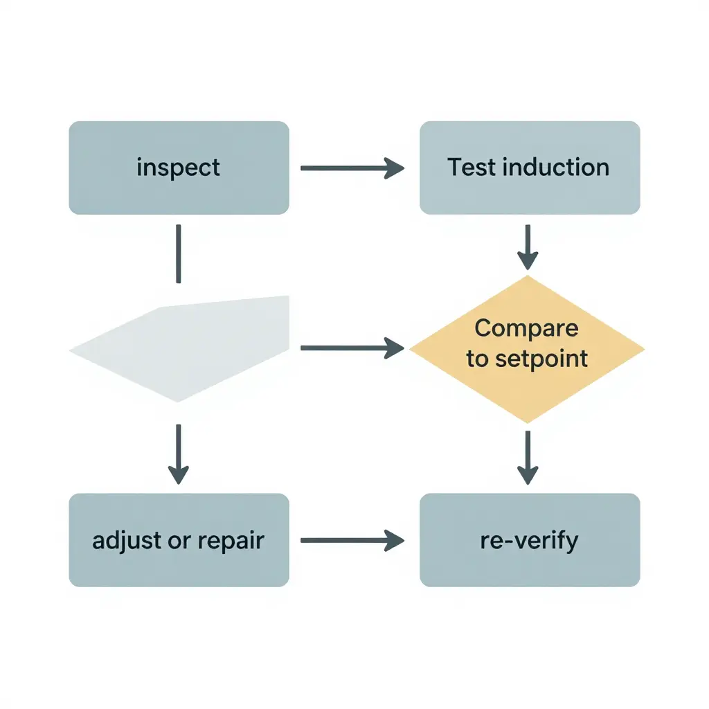
The schematic below shows a five-stage verification loop: inspect, test induction, compare to setpoint, adjust or repair, and re-verify. It is deliberately generic; the same sequence applies to confirming a proportioner against its nameplate ratio, checking a pump discharge against its design curve, or comparing any measured value with a reference. A parameter that falls within tolerance goes straight to re-verification. One that diverges is adjusted or repaired before the test is repeated.
Frequently Asked Questions About Foam Proportioning Drift
What is foam proportioning drift?
Foam proportioning drift is the gradual deviation between the foam concentrate percentage a system actually injects and the percentage it is designed to deliver. Instead of holding a steady 3% or 6% induction rate, the system slowly moves toward under- or over-proportioning over time. The deviation is typically small enough to pass a quick visual check while still falling outside the manufacturer’s stated tolerance band.
Why does foam proportioning drift go undetected on the ramp?
On the ramp, most checks rely on whether foam appears at the nozzle and looks acceptable, not on measured concentration. Visual observation cannot reveal whether the finished mix is 2.6% instead of the required 3.0%. Because the error accumulates gradually and still produces foam that looks normal, routine pre-shift inspections miss it. Only a calibrated refractometer reading taken at the discharge captures the true concentrate ratio.
How often should proportioning be verified?
Verification intervals should follow the manufacturer’s schedule, applicable regulatory guidance, and each vehicle’s service history, with annual testing as a common baseline. High-use vehicles, or those operating in dusty, humid, or extreme-temperature environments, often warrant quarterly checks. Any system repair, concentrate change, or pump overhaul should trigger a verification regardless of where it falls on the calendar.
Can fluorine-free foam concentrates change drift behaviour?
Yes. Fluorine-free concentrates frequently have different viscosity, surface tension, and shear characteristics than legacy AFFF, which can alter how a proportioner meters the concentrate. Some systems require re-calibration or hardware changes when converting to fluorine-free foam. Treat a concentrate switch as a design review, not a simple fluid substitution.
What are the first indicators of drift?
Early indicators include foam that drains too quickly, thinner or wetter blankets than expected, and longer extinguishment times during training evolutions. A gradual increase in concentrate consumption without a matching increase in discharge is another warning sign. A rising refractometer deviation from the target percentage remains the most reliable early indicator of foam proportioning drift.
Does drift ever correct itself?
No. Proportioning drift is a mechanical and fluid-property condition that generally worsens without intervention, not a transient fluctuation. Once a system is confirmed out of tolerance, the cause must be diagnosed and corrected through inspection, cleaning, adjustment, or component replacement. Documenting each reading builds a trend line that exposes slow degradation before it becomes a fireground risk.